Lexus NX: Removal
REMOVAL
CAUTION / NOTICE / HINT
CAUTION:
The engine assembly with hybrid vehicle transaxle assembly is very heavy. Be sure to follow the procedure described in the repair manual, or the engine lifter may suddenly drop.
PROCEDURE
1. REMOVE SERVICE PLUG GRIP
Click here .gif)
2. REMOVE WINDSHIELD WIPER MOTOR AND LINK ASSEMBLY
Click here
3. REMOVE SUSPENSION TOWER DAMPER
-
w/ Performance Damper:
Click here
-
w/o Performance Damper:
Click here
4. REMOVE OUTER COWL TOP PANEL
Click here
5. REMOVE NO. 1 ENGINE COVER SUB-ASSEMBLY
Click here
6. REMOVE AIR CLEANER CAP AND HOSE
Click here
7. REMOVE AIR CLEANER FILTER ELEMENT SUB-ASSEMBLY
Click here
8. REMOVE AIR CLEANER CASE SUB-ASSEMBLY
Click here
9. REMOVE NO. 1 ENGINE UNDER COVER ASSEMBLY
Click here
10. DRAIN HYBRID TRANSAXLE FLUID
Click here
11. REMOVE TRANSMISSION OIL COOLER ASSEMBLY
Click here
12. REMOVE NO. 3 INVERTER COOLING HOSE
Click here
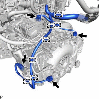
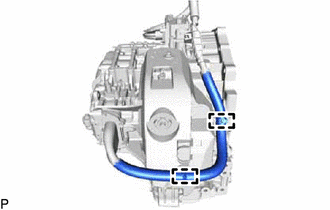
13. DISCONNECT WIRE HARNESS
| (a) Disconnect the 7 clamps, 4 connectors and wire harness from the hybrid vehicle transaxle assembly. |
|
14. DISCONNECT TRANSMISSION CONTROL CABLE ASSEMBLY
Click here
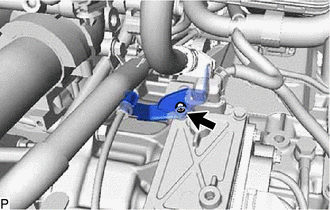
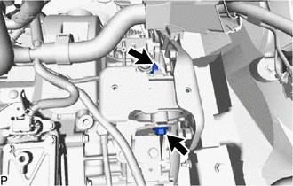
15. REMOVE NO. 2 TRANSMISSION CONTROL CABLE BRACKET
| (a) Remove the bolt and No. 2 transmission control cable bracket. |
|
16. REMOVE FRONT DRIVE SHAFT ASSEMBLY
Click here
17. DISCONNECT RADIATOR RESERVE TANK ASSEMBLY
Click here
18. INSTALL ENGINE HANGER
Click here
19. INSTALL ENGINE SUPPORT BRIDGE
(a) Install SST to the vehicle body as shown in the illustration.
SST: 09940-10020
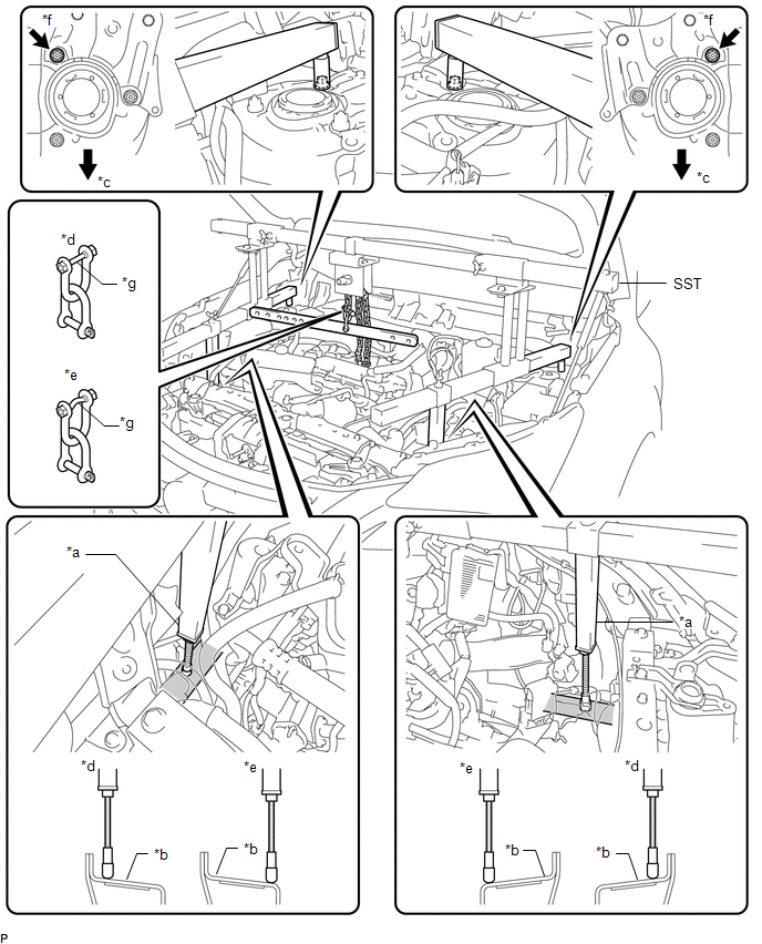
| *a | Support Shaft | *b | Side Member |
| *c | Front Side | *d | Correct |
| *e | Incorrect | *f | Front Suspension Nut |
| *g | Fuse Bolt | - | - |
CAUTION:
Make sure the fuse bolt is not deformed.
NOTICE:
- Prevent SST from contacting the vehicle body or windshield.
- Lightly shake SST by hand to make sure it is securely installed while performing work.
- Set the support shafts on level surfaces.
| (b) Turn the threaded portion of each support shaft to adjust its height and make the SST sub beams parallel to the ground. |
|
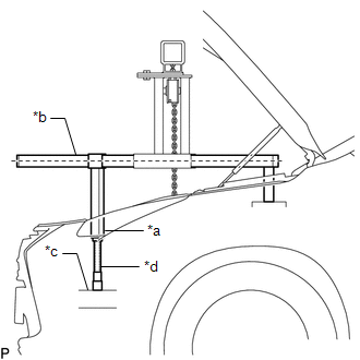
(c) Connect each chain to the division bar with the shackles at the position shown in the illustration.
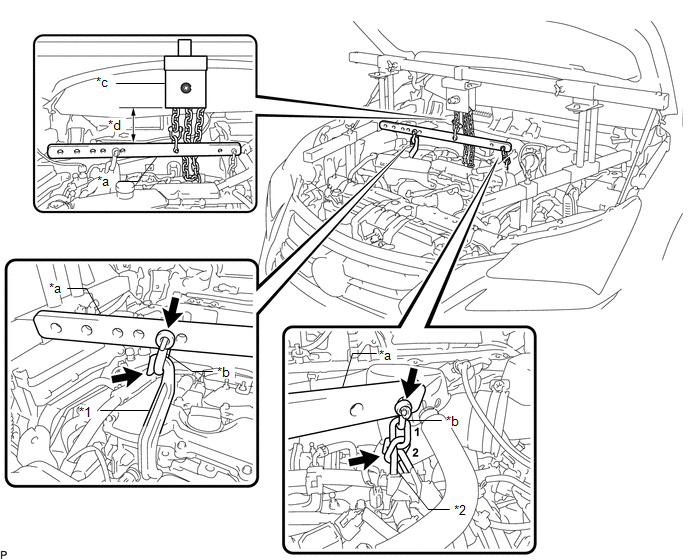
| *1 | No. 1 Engine Hanger | *2 | No. 2 Engine Hanger |
| *a | Division Bar | *b | Shackle |
| *c | Chain Block Assembly | *d | 50 mm (1.97 in.) or more |
(d) Connect the shackle to the No. 1 engine hanger.
(e) Connect the 2nd link of the chain to the No. 2 engine hanger.
(f) Make sure the distance between the chain block assembly and division bar is 50 mm (1.97 in.) or more.
(g) Adjust the position of the chain block assembly so that the chain is perpendicular to the SST main beam and sub beams as shown in the illustration.
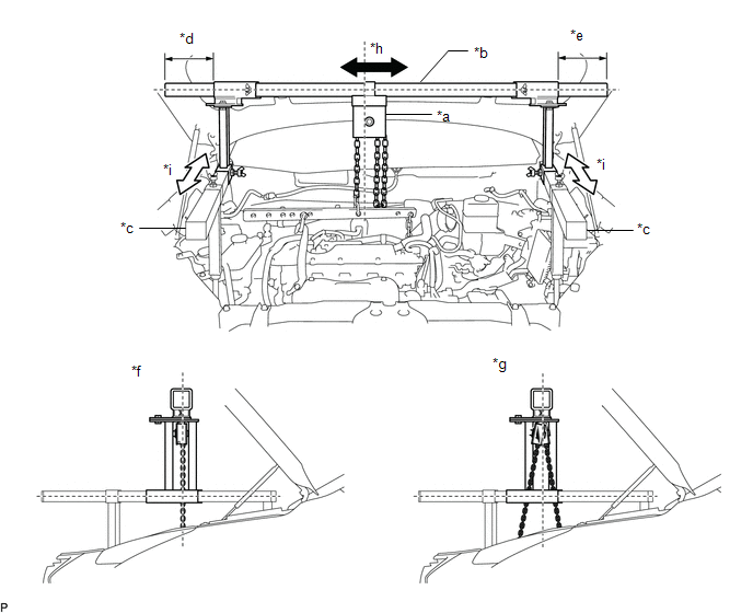
| *a | Chain Block Assembly | *b | Main Beam |
| *c | Sub Beam | *d | Dimension (A) |
| *e | Dimension (B) | *f | Correct |
| *g | Incorrect | *h | Right to Left Adjustment |
| *i | Front to Rear Adjustment | - | - |
CAUTION:
To prevent the engine with hybrid vehicle transaxle assembly from falling, make sure that the dimension (A) and dimension (B) are equal.
(h) Tighten the 6 wing bolts and 2 bolts.
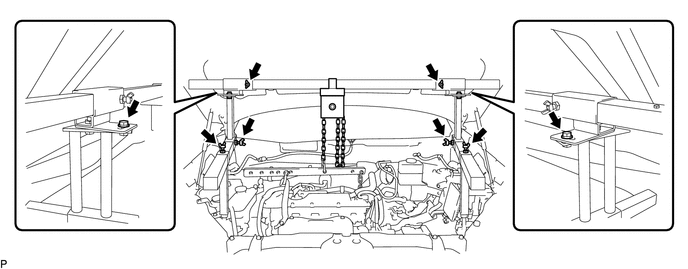
Torque:
Bolt :
30 N·m {306 kgf·cm, 22 ft·lbf}
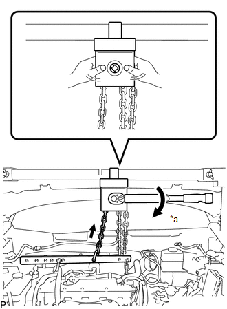
| (i) Tighten the chain block assembly until it cannot be moved any further by hand. NOTICE:
|
|
20. REMOVE FRONT SUSPENSION CROSSMEMBER SUB-ASSEMBLY
Click here
21. SUPPORT HYBRID VEHICLE TRANSAXLE ASSEMBLY
(a) Using a transmission jack attachment, set the hybrid vehicle transaxle assembly on a transmission jack.
NOTICE:
- Secure the hybrid vehicle transaxle assembly to the transmission jack using a suitable adapter, such as a rope or attachment.
- To prevent the No. 2 motor water jacket cover assembly from deforming, do not place any attachments under the No. 2 motor water jacket cover assembly of the hybrid vehicle transaxle assembly.
| (b) Loosen the 9 bolts of the hybrid vehicle transaxle assembly. NOTICE: Do not remove the bolts. |
|
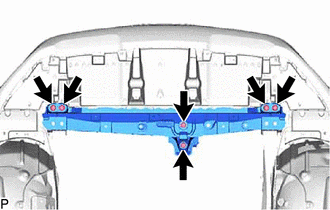
22. REMOVE FRONT CROSSMEMBER SUB-ASSEMBLY
| (a) Remove the 6 bolts and front crossmember sub-assembly. |
|
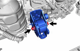
23. REMOVE FRONT ENGINE MOUNTING INSULATOR
| (a) Remove the through bolt, nut and front engine mounting insulator. NOTICE: While holding the nut in place, loosen the through bolt. |
|
24. REMOVE FRONT EXHAUST PIPE ASSEMBLY
Click here
25. DISCONNECT ENGINE MOUNTING INSULATOR LH
| (a) Remove the through bolt and nut and disconnect the engine mounting insulator LH. |
|
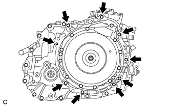
26. REMOVE HYBRID VEHICLE TRANSAXLE ASSEMBLY
(a) Slightly tilt the engine assembly with hybrid vehicle transaxle assembly downward.
NOTICE:
Make sure that the hybrid vehicle transaxle assembly is not tilted excessively so that the engine does not contact the vehicle.
| (b) Remove the 9 bolts and hybrid vehicle transaxle assembly. NOTICE:
|
|
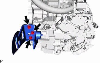
27. REMOVE FRONT ENGINE MOUNTING BRACKET
| (a) Remove the 3 bolts and front engine mounting bracket from the hybrid vehicle transaxle assembly. |
|
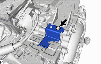
28. REMOVE NO. 3 OIL COOLER TUBE CLAMP
| (a) Remove the bolt and No. 3 oil cooler tube clamp from the hybrid vehicle transaxle assembly. |
|
29. REMOVE ENGINE MOUNTING BRACKET LH
| (a) Remove the 4 bolts and engine mounting bracket LH from the hybrid vehicle transaxle assembly. |
|

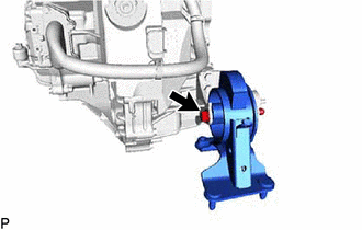
30. REMOVE REAR ENGINE MOUNTING INSULATOR
| (a) Remove the through bolt, nut and rear engine mounting insulator from the rear engine mounting bracket. |
|
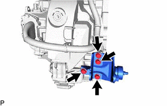
31. REMOVE REAR ENGINE MOUNTING BRACKET
| (a) Remove the 4 bolts and rear engine mounting bracket from the hybrid vehicle transaxle assembly. |
|
32. REMOVE TRANSMISSION OIL COOLER BRACKET
| (a) Remove the 2 bolts and transmission oil cooler bracket from the hybrid vehicle transaxle assembly. |
|
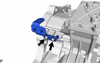
33. REMOVE NO. 1 TRANSMISSION CONTROL CABLE BRACKET
| (a) Remove the 2 bolts and No. 1 transmission control cable bracket from the hybrid vehicle transaxle assembly. |
|
34. REMOVE SHIFT LEVER POSITION SENSOR
Click here
35. REMOVE OIL COOLER TUBE CLAMP
| (a) Remove the 2 bolts and oil cooler tube clamp from the hybrid vehicle transaxle assembly. |
|
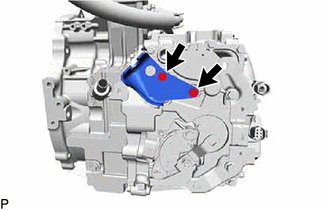
36. REMOVE NO. 2 AUTOMATIC TRANSMISSION CASE COVER
| (a) Remove the bolt, clip and No. 2 automatic transmission case cover from the hybrid vehicle transaxle assembly. |
|
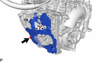
37. REMOVE AUTOMATIC TRANSMISSION CASE COVER
| (a) Detach the 2 clamps and motor cable. |
|
| (b) Detach the 2 guides and remove the automatic transmission case cover from the No. 3 automatic transmission case cover. |
|
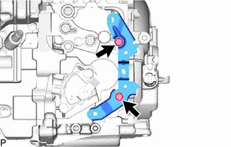
38. REMOVE NO. 3 AUTOMATIC TRANSMISSION CASE COVER
| (a) Remove the 2 bolts, clip and No. 3 automatic transmission case cover from the hybrid vehicle transaxle assembly. |
|
39. REMOVE HYBRID TRANSMISSION MASS DAMPER
| (a) Remove the hybrid transmission mass damper and gasket from the hybrid vehicle transaxle assembly. |
|
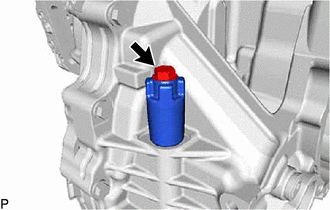
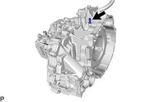
40. REMOVE TRANSAXLE BREATHER PLUG
| (a) Remove the transaxle breather plug from the hybrid vehicle transaxle assembly. |
|
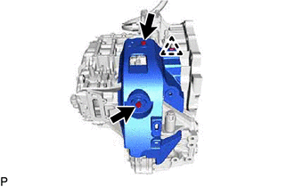
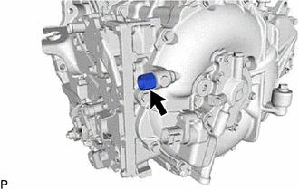
41. REMOVE UNION
| (a) Remove the union and O-ring from the hybrid vehicle transaxle assembly. |
|
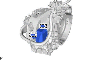
42. REMOVE MOTOR CONNECTOR PROTECTOR
| (a) Remove the 2 bolts and motor connector protector from the hybrid vehicle transaxle assembly. |
|
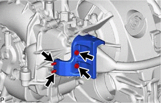
(b) Using an E7 "TORX" socket wrench, remove the 2 stud bolts.
43. REMOVE NO. 2 MOTOR WATER JACKET COVER ASSEMBLY
Click here
44. REMOVE NO. 1 MOTOR WATER JACKET COVER ASSEMBLY
Click here
45. REMOVE NO. 3 MOTOR WATER JACKET COVER ASSEMBLY
Click here
READ NEXT:
 Installation
INSTALLATION PROCEDURE 1. INSTALL NO. 3 MOTOR WATER JACKET COVER ASSEMBLY Click here 2. INSTALL NO. 1 MOTOR WATER JACKET COVER ASSEMBLY Click here 3. INSTALL NO. 2 MOTOR WATER JACKET COVER ASSEMBL
Input Shaft Oil Seal
ComponentsCOMPONENTS ILLUSTRATION *1 HYBRID VEHICLE TRANSAXLE ASSEMBLY *2 INPUT SHAFT TYPE T OIL SEAL ● Non-reusable part MP grease ATF WS - - ReplacementREPLACE
SEE MORE:
Generator High-voltage Circuit
DESCRIPTION The cause of this malfunction may be the generator high-voltage circuit. Check the generator internal resistance and the connection condition of the high-voltage line between the inverter and generator to check whether there is an open or short circuit. Related Parts Check Area Insp
Sensor Power Supply "A" Circuit / Open (P06B0-163,P06D6-511,P06E6-164,P0A1B-786,P0A1B-794,P1C2B-192,P1C73-512,P1CA7-193,P3134-661)
DESCRIPTION The MG ECU, which is built into the inverter with converter assembly, monitors its internal operation and will store DTCs if the system is malfunctioning. If any of the following DTCs are output, replace the inverter with converter assembly. DTC No. Detection Item DTC Detection Co
