Lexus NX: Seat Heater Control (for Front Seat)
Components
COMPONENTS
ILLUSTRATION
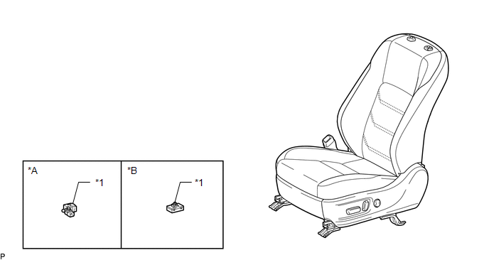
| *A | for L-Sport | *B | for F-Sport |
| *1 | SEAT HEATER CONTROL SUB-ASSEMBLY LH | - | - |
Removal
REMOVAL
CAUTION / NOTICE / HINT
CAUTION:
Wear protective gloves. Sharp areas on the parts may injure your hands.
HINT:
- Use the same procedure for the RH and LH sides.
- The procedure listed below is for the LH side.
PROCEDURE
1. REMOVE FRONT SEAT ASSEMBLY LH
Click here .gif)
2. REMOVE SEAT HEATER CONTROL SUB-ASSEMBLY LH (w/ Seat Heater System)
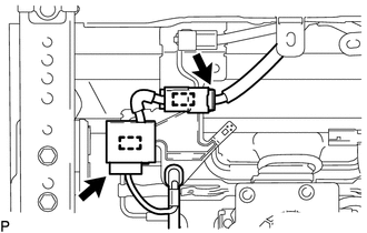
| (a) for L-Sport: (1) Disconnect the 2 connectors. (2) Detach the 2 clamps to remove the seat heater control sub-assembly LH. |
|
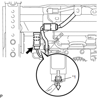
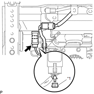
| (b) for F-Sport: (1) Remove the connector lock. (2) Disconnect the seat heater control connector. (3) Detach the clamp to remove the seat heater control sub-assembly LH. |
|
Installation
INSTALLATION
CAUTION / NOTICE / HINT
CAUTION:
Wear protective gloves. Sharp areas on the parts may injure your hands.
HINT:
- Use the same procedure for the RH and LH sides.
- The procedure listed below is for the LH side.
PROCEDURE
1. INSTALL SEAT HEATER CONTROL SUB-ASSEMBLY LH (w/ Seat Heater System)
(a) for L-Sport:
(1) Attach the 2 clamps to install the seat heater control sub-assembly LH.
(2) Connect the 2 connectors.
| (b) for F-Sport: (1) Attach the clamp to install the seat heater control sub-assembly LH. (2) Connect the seat heater control connector. (3) Install the connector lock. |
|
2. INSTALL FRONT SEAT ASSEMBLY LH
Click here .gif)
READ NEXT:
 Components
COMPONENTS ILLUSTRATION *A for RH Side *B for Manual Seat *C for Power Seat - - *1 REAR SEATBACK ASSEMBLY RH *2 REAR SEATBACK BOARD CARPET ASSEMBLY RH *3 REAR SEATB
Removal
REMOVAL CAUTION / NOTICE / HINT CAUTION: Wear protective gloves. Sharp areas on the parts may injure your hands. PROCEDURE 1. REMOVE REAR SEATBACK ASSEMBLY LH (a) for Manual Seat: Click here (b) for
SEE MORE:
Components
COMPONENTS ILLUSTRATION *1 DECK FLOOR BOX LH *2 NO. 3 DECK BOARD SUB-ASSEMBLY *3 REAR DECK FLOOR BOX *4 NEGATIVE AUXILIARY BATTERY TERMINAL N*m (kgf*cm, ft.*lbf): Specified torque - - ILLUSTRATION *1 NO. 1 BLACK OUT TAPE LH *2 NO. 2 BLACK OUT TAPE LH *
Drive Motor "A" Inverter Performance (P0A78-286)
DTC SUMMARY MALFUNCTION DESCRIPTION This DTC indicates a malfunction inside the inverter for the motor. The cause of this malfunction may be one of the following: Area Main Malfunction Description Step Inverter low-voltage circuit The connectors are not connected properly 3 Hybrid
