Lexus NX: Speaker Output Short (B15C3)
DESCRIPTION
This DTC is stored when a malfunction occurs in the speakers.
In addition, the radio receiver assembly detects a malfunction via the stereo component amplifier assembly.
| DTC No. | Detection Item | DTC Detection Condition | Trouble Area |
|---|---|---|---|
| B15C3 | Speaker Output Short | A short is detected in the speaker output circuit |
|
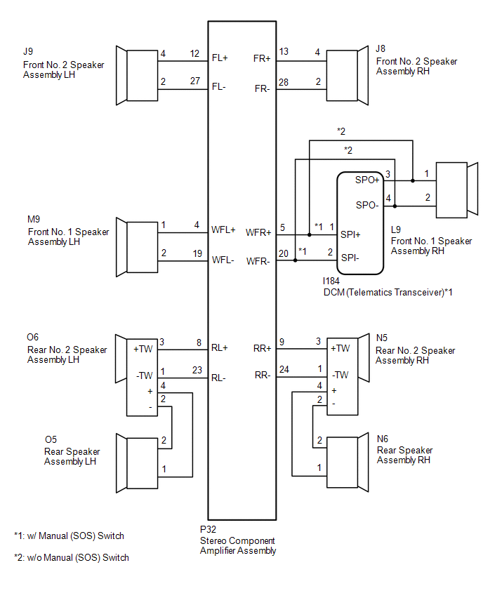
WIRING DIAGRAM
CAUTION / NOTICE / HINT
NOTICE:
When replacing the DCM (telematics transceiver), make sure to replace it with a new one (w/ Manual [SOS] Switch).
HINT:
Depending on the parts that are replaced during vehicle inspection or maintenance, performing initialization, registration or calibration may be needed. Refer to Precaution for Audio and Visual System.
Click here .gif)
PROCEDURE
| 1. | CHECK DTC |
(a) Clear the DTCs.
Click here
(b) Recheck for DTCs and check that no DTCs are output.
Click here
OK:
No DTCs are output.
| OK | .gif) | USE SIMULATION METHOD TO CHECK |
|
.gif)
| 2. | CHECK HARNESS AND CONNECTOR (SPEAKER CIRCUIT) |
-
*1: for LH Side
*2: for RH Side
*3: w/ Manual (SOS) Switch
(a) Disconnect the P32 stereo component amplifier assembly connector.
(b) Disconnect the M9*1 and/or L9*2 front No. 1 speaker assembly connector.
(c) Disconnect the J9*1 and/or J8*2 front No. 2 speaker assembly connector.
(d) Disconnect the O6*1 and/or N5*2 rear No. 2 speaker assembly connector.
(e) Disconnect the O5*1 and/or N6*2 rear speaker assembly connector.
(f) Disconnect the I184 DCM (telematics transceiver) connector.*3
(g) Measure the resistance according to the value(s) in the table below.
Standard Resistance:
for LH Side| Tester Connection | Condition | Specified Condition |
|---|---|---|
| P32-4 (WFL+) - M9-1 | Always | Below 1 Ω |
| P32-19 (WFL-) - M9-2 | Always | Below 1 Ω |
| P32-12 (FL+) - J9-4 | Always | Below 1 Ω |
| P32-27 (FL-) - J9-2 | Always | Below 1 Ω |
| P32-8 (RL+) - O6-3 (+TW) | Always | Below 1 Ω |
| P32-23 (RL-) - O6-1 (-TW) | Always | Below 1 Ω |
| O6-4 (+) - O5-1 | Always | Below 1 Ω |
| O6-2 (-) - O5-2 | Always | Below 1 Ω |
| P32-4 (WFL+) - Body ground | Always | 10 kΩ or higher |
| P32-19 (WFL-) - Body ground | Always | 10 kΩ or higher |
| P32-12 (FL+) - Body ground | Always | 10 kΩ or higher |
| P32-27 (FL-) - Body ground | Always | 10 kΩ or higher |
| P32-8 (RL+) - Body ground | Always | 10 kΩ or higher |
| P32-23 (RL-) - Body ground | Always | 10 kΩ or higher |
| O6-4 (+) - Body ground | Always | 10 kΩ or higher |
| O6-2 (-) - Body ground | Always | 10 kΩ or higher |
| Tester Connection | Condition | Specified Condition |
|---|---|---|
| P32-5 (WFR+) - I184-1 (SPI+) | Always | Below 1 Ω |
| P32-20 (WFR-) - I184-2 (SPI-) | Always | Below 1 Ω |
| I184-3 (SPO+) - L9-1 | Always | Below 1 Ω |
| I184-4 (SPO-) - L9-2 | Always | Below 1 Ω |
| P32-13 (FR+) - J8-4 | Always | Below 1 Ω |
| P32-28 (FR-) - J8-2 | Always | Below 1 Ω |
| P32-9 (RR+) - N5-3 (+TW) | Always | Below 1 Ω |
| P32-24 (RR-) - N5-1 (-TW) | Always | Below 1 Ω |
| N5-4 (+) - N6-1 | Always | Below 1 Ω |
| N5-2 (-) - N6-2 | Always | Below 1 Ω |
| P32-5 (WFR+) - Body ground | Always | 10 kΩ or higher |
| P32-20 (WFR-) - Body ground | Always | 10 kΩ or higher |
| I184-3 (SPO+) - Body ground | Always | 10 kΩ or higher |
| I184-4 (SPO-) - Body ground | Always | 10 kΩ or higher |
| P32-13 (FR+) - Body ground | Always | 10 kΩ or higher |
| P32-28 (FR-) - Body ground | Always | 10 kΩ or higher |
| P32-9 (RR+) - Body ground | Always | 10 kΩ or higher |
| P32-24 (RR-) - Body ground | Always | 10 kΩ or higher |
| N5-4 (+) - Body ground | Always | 10 kΩ or higher |
| N5-2 (-) - Body ground | Always | 10 kΩ or higher |
| Tester Connection | Condition | Specified Condition |
|---|---|---|
| P32-5 (WFR+) - L9-1 | Always | Below 1 Ω |
| P32-20 (WFR-) - L9-2 | Always | Below 1 Ω |
| P32-13 (FR+) - J8-4 | Always | Below 1 Ω |
| P32-28 (FR-) - J8-2 | Always | Below 1 Ω |
| P32-9 (RR+) - N5-3 (+TW) | Always | Below 1 Ω |
| P32-24 (RR-) - N5-1 (-TW) | Always | Below 1 Ω |
| N5-4 (+) - N6-1 | Always | Below 1 Ω |
| N5-2 (-) - N6-2 | Always | Below 1 Ω |
| P32-5 (WFR+) - Body ground | Always | 10 kΩ or higher |
| P32-20 (WFR-) - Body ground | Always | 10 kΩ or higher |
| P32-13 (FR+) - Body ground | Always | 10 kΩ or higher |
| P32-28 (FR-) - Body ground | Always | 10 kΩ or higher |
| P32-9 (RR+) - Body ground | Always | 10 kΩ or higher |
| P32-24 (RR-) - Body ground | Always | 10 kΩ or higher |
| N5-4 (+) - Body ground | Always | 10 kΩ or higher |
| N5-2 (-) - Body ground | Always | 10 kΩ or higher |
| NG | | REPAIR OR REPLACE HARNESS OR CONNECTOR |
|
| 3. | INSPECT FRONT NO. 1 SPEAKER ASSEMBLY |
(a) Remove the front No. 1 speaker assembly.
Click here
(b) Inspect the front No. 1 speaker assembly.
Click here
| NG | | REPLACE FRONT NO. 1 SPEAKER ASSEMBLY |
|
| 4. | INSPECT FRONT NO. 2 SPEAKER ASSEMBLY |
(a) Remove the front No. 2 speaker assembly.
Click here
(b) Inspect the front No. 2 speaker assembly.
Click here
| NG | | REPLACE FRONT NO. 2 SPEAKER ASSEMBLY |
|
| 5. | INSPECT REAR SPEAKER ASSEMBLY |
(a) Remove the rear speaker assembly.
Click here
(b) Inspect the rear speaker assembly.
Click here
| NG | | REPLACE REAR SPEAKER ASSEMBLY |
|
| 6. | CHECK VEHICLE TYPE |
(a) Check the vehicle type.
| Result | Proceed to |
|---|---|
| w/ Manual (SOS) Switch | A |
| w/o Manual (SOS) Switch | B |
| B | | GO TO STEP 8 |
|
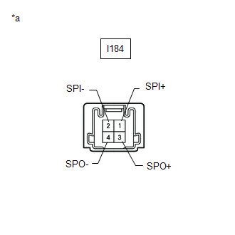
| 7. | INSPECT DCM (TELEMATICS TRANSCEIVER) (SPO+, SPO-, SPI+, SPI-) |
(a) Remove the DCM (telematics transceiver).
Click here
| (b) Measure the resistance according to the value(s) in the table below. Standard Resistance:
|
|
| NG | | REPLACE DCM (TELEMATICS TRANSCEIVER) |
|
| 8. | CHECK REAR NO. 2 SPEAKER ASSEMBLY |
(a) Replace the rear No. 2 speaker assembly with a new or known good one.
Click here
(b) Clear the DTCs.
Click here
(c) Recheck for DTCs and check that no DTCs are output.
Click here
OK:
No DTCs are output.
| OK | | END (REAR NO. 2 SPEAKER ASSEMBLY IS DEFECTIVE) |
| NG | | REPLACE STEREO COMPONENT AMPLIFIER ASSEMBLY |
READ NEXT:
 Stereo Component Amplifier Disconnected (B15D3)
DESCRIPTION The radio receiver assembly and stereo component amplifier assembly are connected by the AVC-LAN communication line. This DTC is stored when an AVC-LAN communication error occurs between t
Display Disconnected (B15D6)
DESCRIPTION The multi-display assembly and radio receiver assembly are connected by the AVC-LAN communication line. This DTC is stored when an AVC-LAN communication error occurs between the multi-disp
Telematics Transceiver Disconnected (B15DB)
DESCRIPTION If the radio receiver assembly cannot detect the DCM (telematics transceiver) for a certain period of time (90 seconds) after the power switch is turned on (IG) and the radio receiver asse
SEE MORE:
Room Light
ComponentsCOMPONENTS ILLUSTRATION *A for Normal Roof *B for Sliding Roof *C for Glass Roof - - *1 SPOT LIGHT ASSEMBLY (ROOM LIGHT) - - RemovalREMOVAL PROCEDURE 1. REMOVE SPOT LIGHT ASSEMBLY (ROOM LIGHT) (a) Using a screwdriver, detach the 4 clips. HINT: Tape the
Steering Knuckle
ComponentsCOMPONENTS ILLUSTRATION *1 FRONT AXLE HUB SUB-ASSEMBLY LH *2 FRONT LOWER BALL JOINT ASSEMBLY LH *3 STEERING KNUCKLE LH *4 FRONT BRAKE DUST COVER N*m (kgf*cm, ft.*lbf): Specified torque ● Non-reusable part RemovalREMOVAL CAUTION / NOTICE / HINT HINT:
