Lexus NX: Room Light
Components
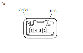
COMPONENTS
ILLUSTRATION
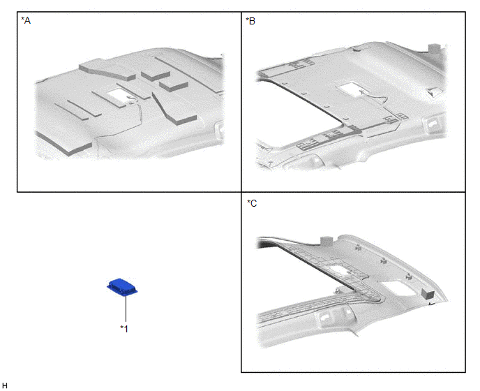
| *A | for Normal Roof | *B | for Sliding Roof |
| *C | for Glass Roof | - | - |
| *1 | SPOT LIGHT ASSEMBLY (ROOM LIGHT) | - | - |
Removal
REMOVAL
PROCEDURE
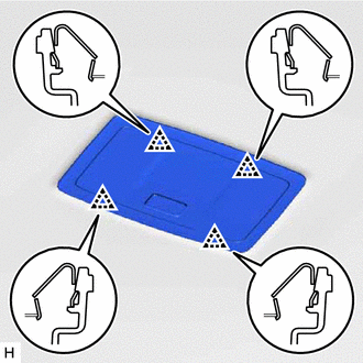
1. REMOVE SPOT LIGHT ASSEMBLY (ROOM LIGHT)
| (a) Using a screwdriver, detach the 4 clips. HINT: Tape the screwdriver tip before use. |
|
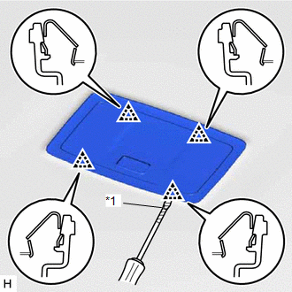
(b) Disconnect the connector and remove the spot light assembly (room light).
Inspection
INSPECTION
PROCEDURE
1. INSPECT SPOT LIGHT ASSEMBLY (ROOM LIGHT)
(a) Inspect the room light.
| (1) Apply battery voltage to the connector and check the light illumination condition. OK:
If the result is not as specified, replace the spot light assembly (room light). |
|
| (b) Inspect the room light (for Door-linked). (1) Apply battery voltage to the connector and check the light illumination condition. OK:
If the result is not as specified, replace the spot light assembly (room light). |
|
| (c) Inspect the switch illumination. (1) Apply battery voltage to the connector and check the light illumination condition. OK:
If the result is not as specified, replace the spot light assembly (room light). |
|
Installation
INSTALLATION
PROCEDURE
1. INSTALL SPOT LIGHT ASSEMBLY (ROOM LIGHT)
| (a) Connect the connector. |
|
(b) Attach the 4 clips to install the spot light assembly (room light).
READ NEXT:
 Vanity Light
ComponentsCOMPONENTS ILLUSTRATION *1 VANITY LIGHT ASSEMBLY *2 VANITY LIGHT BULB *3 VANITY LIGHT HOLDER - - RemovalREMOVAL CAUTION / NOTICE / HINT HINT:
Use the same procedu
Vanity Light Bulb
ReplacementREPLACEMENT CAUTION / NOTICE / HINT HINT:
Use the same procedure for the RH and LH sides.
The procedure listed below is for the LH side.
PROCEDURE 1. DISCONNECT VANITY LIGHT ASSEMB
SEE MORE:
Vehicle Control History
VEHICLE CONTROL HISTORY NOTICE: When checking the vehicle control history, first record the output codes and after clearing the history, check the output history again. CHECK VEHICLE CONTROL HISTORY (FRONT CAMERA SYSTEM) (a) Connect the Techstream to the DLC3. (b) Turn the power switch on (IG). (c)
Inspection
INSPECTION CAUTION / NOTICE / HINT NOTICE:
When using a vise, place aluminum plates between the part and vise.
When using a vise, do not overtighten it.
PROCEDURE 1. INSPECT REAR DRIVE SHAFT ASSEMBLY (a) Check that there is no excessive play in the radial direction of the inboard joint an
