Lexus NX: Terminals Of Ecu
TERMINALS OF ECU
CHECK DCM (TELEMATICS TRANSCEIVER)
| Terminal No. (Symbol) | Wiring Color | Terminal Description | Condition | Specified Condition |
|---|---|---|---|---|
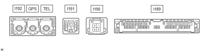
| I183-1 (+B) - I183-20 (E) | Y - W-B | Power source (+B) | Power switch off | 11 to 14 V |
| I183-3 (SIG-) - I183-20 (E) | G - W-B | Ground | Always | Below 1 V |
| I183-4 (IND1) - I183-20 (E) | LG - W-B | Manual (SOS) switch red indicator illumination signal | For 2 seconds after turning the power switch on (IG) | 1 to 8.5 V |
| Power switch off | Below 1 V | |||
| I183-5 (MCVD) - I183-20 (E) | B - W-B | Telephone microphone assembly power supply | Power switch on (IG) | 4 to 6 V |
| Power switch off | Below 1 V | |||
| I183-6 (MCI+) - I183-20 (E) | W - W-B | Receive microphone voice signal | Voice being input to telephone microphone assembly | A waveform synchronized with microphone voice signal is input |
| I183-7 (MCI-) - I183-20 (E) | R - W-B | Receive microphone voice signal | Always | Below 1 V |
| I183-13 (GSW) - I183-20 (E) | BE - W-B | Collision detection signal | Power switch on (IG) | Pulse generation (Refer to waveform 1) |
| I183-14 (MUTE) - I183-20 (E) | B - W-B | MUTE Signal | Audio system playing | 3.5 V or higher |
| Emergency call mode | Below 1 V | |||
| I183-15 (USBV) - I183-20 (E) | G - W-B | DCM (telematics transceiver) power supply signal | Power switch on (IG) | 4.75 to 5.25 V |
| Power switch off | Below 1 V | |||
| I183-16 (MCO+) - I183-20 (E) | G - W-B | Microphone voice signal | Voice being input to telephone microphone assembly | A waveform synchronized with microphone voice signal is input |
| I183-17 (VOT+) - I183-20 (E) | R - W-B | Sent voice signal | Calling while using the operator service | A waveform synchronized with the received voice is output |
| I183-18 (VOR+) - I183-20 (E) | B - W-B | Receive voice signal | Receiving a call while using the operator service | A waveform synchronized with the sent voice is output |
| I183-19 (IG2) - I183-20 (E) | R - W-B | Power source (IG) | Power switch on (IG) | 11 to 14 V |
| Power switch off | Below 1 V | |||
| I183-20 (E) - Body ground | W-B - Body ground | Ground | Always | Below 1 Ω |
| I183-21 (SIG1) - I183-3 (SIG-) | V - G | Manual (SOS) switch button condition signal | Manual (SOS) switch not pressed | 1.3 to 1.9 V |
| Manual (SOS) switch pressed | 0.5 to 0.8 V | |||
| I183-22 (IND2) - I183-20 (E) | L - W-B | Manual (SOS) switch green indicator illumination signal | For 2 seconds after turning the power switch on (IG) | 1 to 8.5 V |
| Power switch off | Below 1 V | |||
| I183-23 (SGND) - I183-20 (E) | Shielded - W-B | Shield ground | Always | Below 1 Ω |
| I183-25 (CANP) | Y | CAN communication signal | - | - |
| I183-26 (CANN) | W | CAN communication signal | - | - |
| I183-31 (USBG) - Body ground | P - Body ground | Shield ground | Always | Below 1 Ω |
| I183-32 (MCO-) - I183-20 (E) | R - W-B | Microphone voice signal | Always | Below 1 V |
| I183-33 (VOT-) - I183-20 (E) | G - W-B | Sent voice signal | Calling while using the operator service | A waveform synchronized with the received voice is output |
| I183-34 (VOR-) - I183-20 (E) | W - W-B | Receive voice signal | Receiving a call while using the operator service | A waveform synchronized with the sent voice is output |
| I184-1 (SPI+) - I183-20 (E) | P - W-B*1 W - W-B*2 | Sound signal | Audio system playing | A waveform synchronized with sound signals is output |
| I184-2 (SPI-) - I183-20 (E) | R - W-B | Sound signal | Audio system playing | A waveform synchronized with sound signals is output |
| I184-3 (SPO+) - I183-20 (E) | Y - W-B*1 R - W-B*2 | Sound signal | Audio system playing, or emergency call mode | A waveform synchronized with sound signals is output |
| I184-4 (SPO-) - I183-20 (E) | B - W-B*1 W - W-B*2 | Sound signal | Audio system playing, or emergency call mode | A waveform synchronized with sound signals is output |
| I185-1 (USB-) | # | USB communication line | - | - |
| I185-2 (USB+) | # | USB communication line | - | - |
| I185-3 (USBS) - Body ground | Shielded - Body ground | Shield ground | Always | Below 1 Ω |
- *1: w/ Navigation System
- *2: w/o Navigation System
- #: There is no wire color information
(a) Oscilloscope waveform:
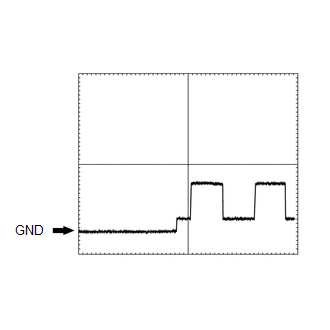
(1) Waveform 1
| Item | Condition |
|---|---|
| Tester connection | I183-13 (GSW) - I183-20 (E) |
| Tool setting | 5.0 V/DIV., 20 ms./DIV. |
| Vehicle condition | Power switch on (IG) |
CHECK RADIO RECEIVER ASSEMBLY
w/ Navigation System: Click here .gif)
w/o Navigation System: Click here
CHECK STEREO COMPONENT AMPLIFIER ASSEMBLY
w/ Navigation System: Click here
w/o Navigation System: Click here
CHECK NAVIGATION ECU (w/ Navigation System)
Click here
READ NEXT:
 Diagnosis System
DIAGNOSIS SYSTEM DESCRIPTION (a) The DCM (telematics transceiver) control the vehicle safety connect system functions. Safety connect system data and Diagnostic Trouble Codes (DTCs) can be read throug
Dtc Check / Clear
DTC CHECK / CLEAR CHECK DTC (a) Connect the Techstream to the DLC3. (b) Turn the power switch on (IG). (c) Turn the Techstream on. (d) Enter the following menus: Body Electrical / Telematics / Trouble
Data List / Active Test
DATA LIST / ACTIVE TEST DATA LIST NOTICE: In the table below, the values listed under "Normal Condition" are reference values. Do not depend solely on these reference values when deciding whether a pa
SEE MORE:
Components
COMPONENTS ILLUSTRATION *1 DECK FLOOR BOX LH *2 NO. 3 DECK BOARD SUB-ASSEMBLY *3 REAR DECK FLOOR BOX *4 NEGATIVE AUXILIARY BATTERY TERMINAL N*m (kgf*cm, ft.*lbf): Specified torque - - ILLUSTRATION *A for Driver Side *B for Front Passenger Side *1 FRO
Vehicle Speed Signal (C1541)
DESCRIPTION The power steering ECU assembly receives vehicle speed signals from the skid control ECU (brake booster with master cylinder assembly) via CAN communication. The ECU provides appropriate assisting force in accordance with the vehicle speed based on the signals. DTC No. Detection Ite
