Lexus NX: Adjustment
ADJUSTMENT
CAUTION / NOTICE / HINT
HINT:
- Use the same procedure for the RH and LH sides.
- The procedure listed below is for the LH side.
-
Centering bolts are used to mount the door hinge to the vehicle body and door. The door cannot be adjusted with the centering bolts on. Substitute the centering bolts for standard bolts when making adjustments.
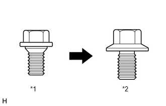
*1
Centering Bolt
*2
Standard Bolt
-
A bolt without a torque specification is shown in the standard bolt chart.
Click here
.gif)
PROCEDURE
1. INSPECT FRONT DOOR PANEL SUB-ASSEMBLY LH
(a) Check that the clearance measurements of areas A to H are within the standard ranges.
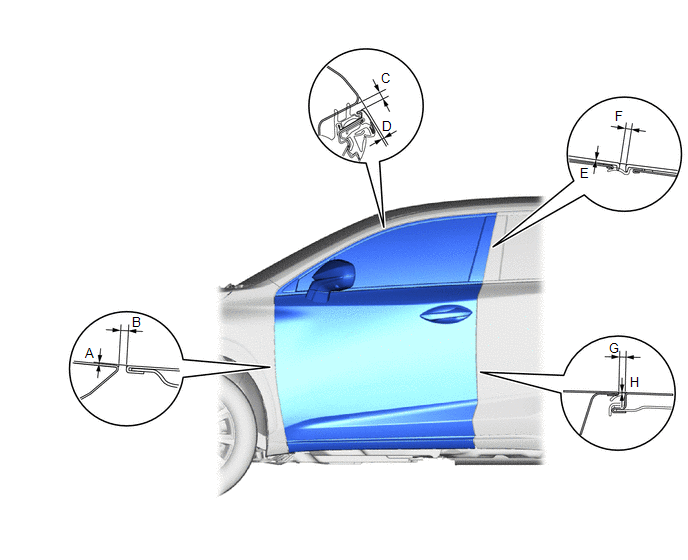
Standard Clearance:
| Area | Measurement | Area | Measurement |
|---|---|---|---|
| A | -1.5 to 1.5 mm (-0.0591 to 0.0591 in.) | B | 2.0 to 5.0 mm (0.0787 to 0.1969 in.) |
| C | 2.95 to 6.95 mm (0.1161 to 0.2736 in.) | D | -0.35 to 3.65 mm (-0.0138 to 0.1437 in.) |
| E (Reference) | 0 mm (0 in.) | F (Reference) | 4.1 mm (0.1614 in.) |
| G | 2.6 to 5.0 mm (0.1024 to 0.1969 in.) | H | -1.2 to 1.2 mm (-0.0472 to 0.0472 in.) |
2. ADJUST FRONT DOOR PANEL SUB-ASSEMBLY LH
| (a) Using SST, loosen the hinge bolts on the body and adjust the door position. SST: 09812-00010 |
|
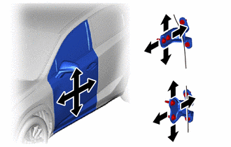
(b) Tighten the hinge bolts on the body after the adjustment.
Torque:
26 N·m {265 kgf·cm, 19 ft·lbf}
| (c) Loosen the hinge bolts on the door and adjust the door position. |
|
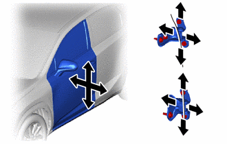
(d) Tighten the hinge bolts on the door after the adjustment.
Torque:
21 N·m {214 kgf·cm, 15 ft·lbf}
| (e) Detach the 4 claws and remove the striker cover. |
|
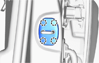
| (f) Using a T40 "TORX" socket wrench, adjust the striker position by slightly loosening the striker mounting screws and hitting the striker with a plastic-faced hammer. Torque: 23 N·m {235 kgf·cm, 17 ft·lbf} |
|
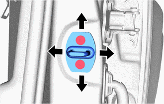
(g) Attach the 4 claws and install the striker cover.
READ NEXT:
 Reassembly
REASSEMBLY CAUTION / NOTICE / HINT HINT:
Use the same procedure for the RH and LH side.
The procedure listed below is for the LH side.
A bolt without a torque specification is shown in the stan
Front Door Opening Trim Weatherstrip
ComponentsCOMPONENTS ILLUSTRATION *1 DOOR SCUFF PLATE ASSEMBLY LH *2 FRONT DOOR OPENING TRIM WEATHERSTRIP LH RemovalREMOVAL CAUTION / NOTICE / HINT HINT:
Use the same procedure for t
SEE MORE:
Inspection
INSPECTION PROCEDURE 1. INSPECT BACK DOOR LOCK ASSEMBLY (BACK DOOR COURTESY SWITCH) (a) w/o Power Back Door: (1) Move the back door lock assembly to the lock position. *1 Latch *a Component without harness connected (Back Door Lock Assembly (Back Door Courtesy Switch)) *b
System Description
SYSTEM DESCRIPTION HEADUP DISPLAY SYSTEM DESCRIPTION HINT:
The meter mirror sub-assembly receives signals from the combination meter assembly via the CAN communication line. Information is displayed on the front window based on received signals.
The meter mirror sub-assembly receives navigation
