Lexus NX: Blind Spot Monitor Main Switch
Inspection
INSPECTION
PROCEDURE
1. INSPECT COMBINATION SWITCH ASSEMBLY (BLIND SPOT MONITOR MAIN SWITCH)
(a) Remove the combination switch assembly.
Click here .gif)
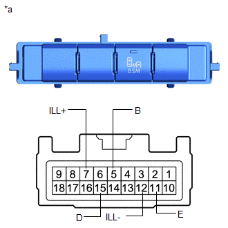
| (b) Measure the resistance according to the value(s) in the table below. Standard Resistance:
If the result is not as specified, replace the combination switch assembly (blind spot monitor main switch). |
|
(c) Check that the switch illuminates.
(1) Apply battery voltage to the combination switch assembly (blind spot monitor main switch) and check that the switch illuminates.
OK:
| Connection | Specified Condition |
|---|---|
| Battery positive (+) → Terminal 7 (ILL+) Battery negative (-) → Terminal 12 (ILL-) | Illuminates |
If the result is not as specified, replace the combination switch assembly (blind spot monitor main switch).
(d) Check that the switch indicator illuminates.
(1) Apply battery voltage to the combination switch assembly (blind spot monitor main switch) and check operation of the switch as shown in the table below.
OK:
| Connection | Switch Condition | Specified Condition |
|---|---|---|
| Battery positive (+) → Terminal 5 (B) Battery negative (-) → Terminal 11 (E) | Blind spot monitor main switch on (not protruding) | Indicator Illuminates |
If the result is not as specified, replace the back sonar or combination switch assembly (blind spot monitor main switch).
(e) Install the combination switch assembly.
Click here
READ NEXT:
 Blind Spot Monitor Sensor
RemovalREMOVAL CAUTION / NOTICE / HINT NOTICE:
Avoid any impact to the blind spot monitor sensor.
Do not drop the blind spot monitor sensor. If it is dropped, replace it with a new one.
PROCE
Precaution
PRECAUTION PRECAUTIONS FOR BLIND SPOT MONITOR SYSTEM (a) The blind spot monitor function may not detect vehicles correctly in the following conditions: (1) When the sensor is misaligned due to a stron
SEE MORE:
Components
COMPONENTS ILLUSTRATION *1 CLEARANCE LIGHT ASSEMBLY LH *2 CLEARANCE LIGHT ASSEMBLY RH *3 HOOD TO FRONT END PANEL SEAL *4 NO. 3 ENGINE ROOM WIRE *5 RADIATOR GRILLE SUB-ASSEMBLY *6 OUTSIDE MOULDING RETAINER ILLUSTRATION *A w/ Panoramic View Monitor System *B
Camera Heater
ComponentsCOMPONENTS ILLUSTRATION *1 FORWARD RECOGNITION WITH HEATER HOOD SUB-ASSEMBLY - - RemovalREMOVAL PROCEDURE 1. REMOVE FORWARD RECOGNITION CAMERA Click here 2. REMOVE FORWARD RECOGNITION WITH HEATER HOOD SUB-ASSEMBLY NOTICE:
Do not touch the inner surface of the forward re
