Lexus NX: Disassembly
DISASSEMBLY
CAUTION / NOTICE / HINT
NOTICE:
- When using a vise, place aluminum plates between the part and vise.
- When using a vise, do not overtighten it.
PROCEDURE
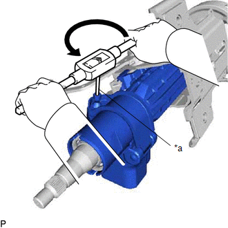
1. REMOVE STEERING LOCK ACTUATOR ASSEMBLY
(a) Secure the electric power steering column sub-assembly in a vise.
(b) Using a center punch, mark the center of the tapered-head bolts.
(c) Using a 3 to 4 mm (0.119 to 0.157 in.) diameter drill bit, drill a hole in the tapered-head bolt.
| (d) Using a screw extractor, remove the tapered-head bolt, and then remove the steering lock actuator assembly from the electric power steering column sub-assembly. |
|
2. REMOVE WIRE HARNESS BRACKET
(a) Lift in the direction (1) indicated by the arrow shown in the illustration, and pull in the direction (2) to detach the claw.
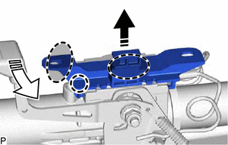
 | Place Hand Here |
.png) | Remove in this Direction (1) |
.png) | Remove in this Direction (2) |
(b) Pull in the direction indicated by the arrow to detach the guide and remove the bracket from the steering column assembly.
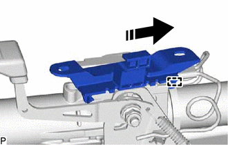
| | Remove in this Direction |
3. REMOVE POWER STEERING ECU ASSEMBLY
Click here .gif)
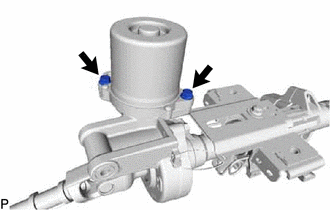
4. REMOVE POWER STEERING MOTOR ASSEMBLY
| (a) Remove the 2 bolts and power steering motor assembly. |
|
READ NEXT:
 Inspection
INSPECTION CAUTION / NOTICE / HINT NOTICE:
When using a vise, place aluminum plates between the part and vise.
When using a vise, do not overtighten it.
PROCEDURE 1. INSPECT ELECTRIC POWER STE
Reassembly
REASSEMBLY CAUTION / NOTICE / HINT NOTICE:
When using a vise, place aluminum plates between the part and vise.
When using a vise, do not overtighten it.
PROCEDURE 1. INSTALL POWER STEERING MOT
Installation
INSTALLATION CAUTION / NOTICE / HINT NOTICE:
Do not replace the spiral with sensor cable sub-assembly with the battery connected and the engine switch on (IG).
Do not rotate the spiral with senso
SEE MORE:
Network Gateway Ecu
ComponentsCOMPONENTS ILLUSTRATION *1 NETWORK GATEWAY ECU - - RemovalREMOVAL PROCEDURE 1. REMOVE ECU INTEGRATION BOX RH Click here 2. REMOVE NETWORK GATEWAY ECU (a) Detach the 2 claws and remove the network gateway ECU. InstallationINSTALLATION PROCEDURE 1. INSTALL NETWORK GATEWAY
Disassembly
DISASSEMBLY CAUTION / NOTICE / HINT NOTICE:
When using a vise, place aluminum plates between the part and vise.
When using a vise, do not overtighten it.
HINT:
Use the same procedure for the RH and LH sides.
The procedure listed below is for the LH side.
PROCEDURE 1. DISCONNECT REAR
