Lexus NX: Disassembly
DISASSEMBLY
CAUTION / NOTICE / HINT
NOTICE:
- When using a vise, place aluminum plates between the part and vise.
- When using a vise, do not overtighten it.
HINT:
- Use the same procedure for the RH and LH sides.
- The procedure listed below is for the LH side.
PROCEDURE
1. DISCONNECT REAR NO. 2 DRIVE SHAFT INBOARD JOINT BOOT CLAMP LH
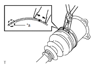
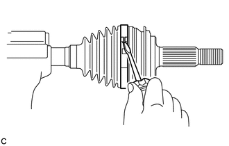
| *a | Claw Engagement |
(a) Using needle-nose pliers, detach the claw engagement and disconnect the rear No. 2 drive shaft inboard joint boot clamp LH.
2. DISCONNECT REAR DRIVE SHAFT INBOARD JOINT BOOT CLAMP LH
HINT:
Use the same procedure described for the rear No. 2 drive shaft inboard joint boot clamp LH.
3. DISCONNECT INBOARD JOINT BOOT
(a) Disconnect the inboard joint boot from the rear drive shaft inboard joint assembly.
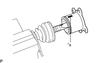
4. REMOVE REAR DRIVE SHAFT INBOARD JOINT ASSEMBLY LH
(a) Remove any old grease from the rear drive shaft inboard joint assembly LH.
| (b) Put matchmarks on the rear drive shaft inboard joint assembly LH and rear drive shaft outboard joint shaft assembly LH. NOTICE: Do not use a punch to make the matchmarks. |
|
(c) Remove the rear drive shaft inboard joint assembly LH from the rear drive shaft outboard joint shaft assembly LH.
NOTICE:
Do not drop the balls.
| (d) Put matchmarks on the rear drive shaft outboard joint shaft assembly LH, inner race and ball cage. NOTICE: Do not use a punch to make the matchmarks. |
|
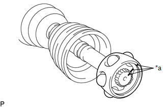
(e) Remove the 6 balls.
NOTICE:
Do not drop the balls.
(f) Slide the ball cage toward the outboard joint side.
| (g) Using a snap ring expander, remove the snap ring. |
|
| (h) Using a brass bar and a hammer, remove the inner race from the rear drive shaft outboard joint shaft assembly LH. NOTICE: Do not drop the inner race. |
|
(i) Remove the ball cage.
(j) Remove the rear No. 2 rear drive shaft inboard joint boot clamp LH, rear drive shaft inboard joint boot and rear drive shaft inboard joint boot clamp LH.
5. DISCONNECT REAR NO. 2 DRIVE SHAFT OUTBOARD JOINT BOOT CLAMP LH
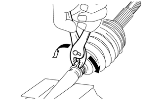
(a) Using needle-nose pliers, detach the claw engagement and disconnect the rear No. 2 drive shaft outboard joint boot clamp LH.
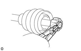
6. DISCONNECT REAR DRIVE SHAFT OUTBOARD JOINT BOOT CLAMP LH
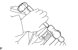
| (a) Using pliers, grasp the rear drive shaft outboard joint boot clamp LH and move the rear drive shaft outboard joint boot clamp LH as shown in the illustration to disconnect the rear drive shaft outboard joint boot clamp LH from the outboard joint boot. |
|
7. REMOVE OUTBOARD JOINT BOOT
(a) Remove the rear drive shaft outboard joint boot clamp LH, outboard joint boot and rear No. 2 drive shaft outboard joint boot clamp LH from the rear drive shaft outboard joint shaft assembly LH.
(b) Remove any old grease from the rear drive shaft outboard joint shaft assembly LH.
READ NEXT:
 Inspection
INSPECTION CAUTION / NOTICE / HINT NOTICE:
When using a vise, place aluminum plates between the part and vise.
When using a vise, do not overtighten it.
PROCEDURE 1. INSPECT REAR DRIVE SHAFT A
Reassembly
REASSEMBLY CAUTION / NOTICE / HINT NOTICE:
When using a vise, place aluminum plates between the part and vise.
When using a vise, do not overtighten it.
HINT:
Use the same procedure for the
Installation
INSTALLATION CAUTION / NOTICE / HINT HINT:
Use the same procedure for the RH and LH sides.
The procedure listed below is for the LH side.
PROCEDURE 1. INSTALL REAR DRIVE SHAFT ASSEMBLY LH (
SEE MORE:
Removal
REMOVAL PROCEDURE 1. DRAIN ENGINE COOLANT Click here 2. REMOVE FAN AND GENERATOR V BELT Click here 3. REMOVE RADIATOR RESERVE TANK ASSEMBLY (a) Slide the 2 clamps and disconnect the water by-pass hose and No. 2 water by-pass hose from the radiator reserve tank assembly. (b) Rem
Components
COMPONENTS ILLUSTRATION *A for RH Side - - *1 REAR NO. 1 SEAT HEADREST SUPPORT ASSEMBLY *2 REAR SEAT CUSHION MOULDING RH *3 REAR SEAT CUSHION MOULDING RH *4 REAR SEAT HEADREST ASSEMBLY *5 REAR SEAT INNER WITH CENTER BELT ASSY RH *6 REAR SEATBACK BOARD CARPET A
