Lexus NX: Inspection
INSPECTION
CAUTION / NOTICE / HINT
NOTICE:
- When using a vise, place aluminum plates between the part and vise.
- When using a vise, do not overtighten it.
PROCEDURE
1. INSPECT TIE ROD END SUB-ASSEMBLY LH
| (a) Secure the tie rod end between aluminum plates in a vise. NOTICE: Do not overtighten the vise. |
|
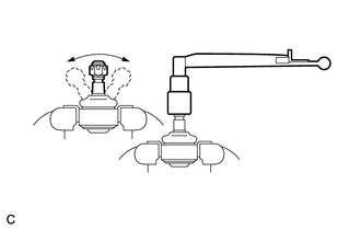
(b) Install the nut to the stud bolt.
(c) Flip the ball joint back and forth 5 times.
(d) Set a torque wrench on the nut, turn the ball joint continuously at a rate of 3 to 5 seconds per turn, and check the turning torque on the 5th turn.
Standard turning torque:
0.98 to 3.92 N*m (10.0 to 39.9 kgf*cm, 8.68 to 34.6 in.*lbf)
If the turning torque is not within the specified range, replace the tie rod end sub-assembly LH with a new one.
2. INSPECT TIE ROD END SUB-ASSEMBLY RH
HINT:
Use the same procedure described for the LH side.
3. INSPECT TOTAL PRELOAD
NOTICE:
Inspect the total preload in a no-load condition by removing the tie rod end sub-assemblies RH and LH, and steering rack boots.
| (a) Install SST to the pinion shaft and turn it left and right 5 times or more. SST: 09616-00011 |
|
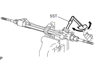
(b) Using a torque wrench and SST, turn the pinion shaft continuously at a rate of 4 to 6 seconds per turn to inspect the total preload of the steering gear assembly.
Total preload:
0.7 to 1.25 N*m (8 to 12 kgf*cm, 7 to 11 in.*lbf)
NOTICE:
Perform the inspection with the steering rack centered.
If the total preload is not within the specified range, replace the steering gear assembly with a new one.
READ NEXT:
 Reassembly
REASSEMBLY PROCEDURE 1. INSTALL NO. 2 STEERING RACK BOOT (a) Apply lithium soap base glycol grease to the inside of the steering rack end. *1 Rack Housing *2 Steering Rack End
Installation
INSTALLATION PROCEDURE 1. INSTALL STEERING GEAR ASSEMBLY (a) Install the steering gear assembly to the front suspension crossmember with the 2 bolts and 2 nuts. Torque: 110 N·m {1122 kgf·cm, 81 ftÂ
SEE MORE:
Replacement
REPLACEMENT CAUTION / NOTICE / HINT HINT:
Use the same procedure for the RH and LH sides.
The following procedure is for the LH side.
NOTICE:
When the brake pedal is first depressed after replacing the brake pads or pushing back the disc brake piston, DTC C1214 may be output. As there is
Diagnosis System
DIAGNOSIS SYSTEM DESCRIPTION When troubleshooting OBD II (On-Board Diagnostics) vehicles, the Techstream (complying with SAE J1978) must be connected to the DLC3 (Data Link Connector 3) of the vehicle. Various data in the vehicle's ECM (Engine Control Module) can be then read. OBD II regulations re
