Lexus NX: Inspection
INSPECTION
PROCEDURE
1. INSPECT HEADUP DISPLAY SWITCH ASSEMBLY
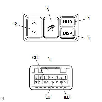
| *1 | HUD Switch |
| *2 | TILT Switch |
| *3 | RHEOSTAT Switch |
| *4 | DISP Switch |
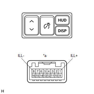
| *a | Component without harness connected (Headup Display Switch Assembly) |
(a) Check the resistance.
Measure the resistance according to the value(s) in the table below.
Standard Resistance:
| Tester Connection | Switch Condition | Specified Condition |
|---|---|---|
| 12 (ILU) - 6 (CH) | HUD switch off (Not pushed) | 100 kΩ |
| 10 (ILD) - 6 (CH) | 100 kΩ | |
| 12 (ILU) - 6 (CH) | HUD switch on (Pushed) | Below 1 Ω |
| 10 (ILD) - 6 (CH) | 100 kΩ | |
| 12 (ILU) - 6 (CH) | TILT switch (UP) on (Pushed) | 100 kΩ |
| 10 (ILD) - 6 (CH) | 3210 Ω | |
| 12 (ILU) - 6 (CH) | TILT switch off (Not pushed) | 100 kΩ |
| 10 (ILD) - 6 (CH) | 100 kΩ | |
| 12 (ILU) - 6 (CH) | TILT switch (DOWN) on (Pushed) | 100 kΩ |
| 10 (ILD) - 6 (CH) | 1010 Ω | |
| 12 (ILU) - 6 (CH) | RHEOSTAT switch (ILL UP) on (Pushed) | 100 kΩ |
| 10 (ILD) - 6 (CH) | 330 Ω | |
| 12 (ILU) - 6 (CH) | RHEOSTAT switch off (Not pushed) | 100 kΩ |
| 10 (ILD) - 6 (CH) | 100 kΩ | |
| 12 (ILU) - 6 (CH) | RHEOSTAT switch (ILL DOWN) on (Pushed) | 100 kΩ |
| 10 (ILD) - 6 (CH) | Below 1 Ω | |
| 12 (ILU) - 6 (CH) | DISP switch off (Not pushed) | 100 kΩ |
| 10 (ILD) - 6 (CH) | 100 kΩ | |
| 12 (ILU) - 6 (CH) | DISP switch on (Pushed) | 330 Ω |
| 10 (ILD) - 6 (CH) | 100 kΩ |
If the result is not as specified, replace the headup display switch assembly.
| (b) Check the illumination. Apply battery voltage to the connector and check the illumination condition. OK:
If the result is not as specified, replace the headup display switch assembly. |
|
READ NEXT:
 Installation
INSTALLATION PROCEDURE 1. INSTALL HEADUP DISPLAY SWITCH ASSEMBLY (a) Attach the 4 claws to install the headup display switch assembly. 2. INSTALL NO. 1 SWITCH HOLE BASE Click here 3
Parts Location
PARTS LOCATION ILLUSTRATION *1 HEADUP DISPLAY SWITCH ASSEMBLY *2 METER MIRROR SUB-ASSEMBLY *3 FORWARD RECOGNITION CAMERA *4 NO. 2 ENGINE ROOM RELAY BLOCK - ECU-B NO.1 FUSE *5
SEE MORE:
Reassembly
REASSEMBLY CAUTION / NOTICE / HINT NOTICE:
When using a vise, place aluminum plates between the part and vise.
When using a vise, do not overtighten it.
PROCEDURE 1. INSTALL FRONT DRIVE SHAFT BEARING (for RH Side) (a) Using SST and a press, press in the front drive inboard joint assembly
If you have a flat tire
Your vehicle is equipped with a
spare tire. The flat tire can be
replaced with the spare tire.
WARNING
■If you have a flat tire
Do not continue driving with a flat tire.
Driving even a short distance with a flat
tire can damage the tire and the wheel
beyond repair, which could result in
