Lexus NX: Removal
REMOVAL
PROCEDURE
1. REMOVE CONSOLE ARMREST ASSEMBLY
Click here .gif)
2. REMOVE UPPER REAR CONSOLE PANEL
Click here
3. REMOVE UPPER NO. 2 CONSOLE PANEL GARNISH
Click here
4. REMOVE UPPER NO. 1 CONSOLE PANEL GARNISH
Click here
5. REMOVE INSTRUMENT SIDE PANEL LH
Click here
6. REMOVE NO. 1 INSTRUMENT PANEL SAFETY PAD SUB-ASSEMBLY
Click here
7. REMOVE NO. 1 INSTRUMENT PANEL UNDER COVER SUB-ASSEMBLY
Click here
8. REMOVE LOWER NO. 1 INSTRUMENT PANEL FINISH PANEL
Click here
9. REMOVE NO. 1 SWITCH HOLE BASE
Click here
10. REMOVE INSTRUMENT SIDE PANEL RH
Click here
11. REMOVE NO. 2 INSTRUMENT PANEL SAFETY PAD SUB-ASSEMBLY
Click here
12. REMOVE INSTRUMENT PANEL FINISH PLATE
Click here
13. REMOVE MULTI-DISPLAY ASSEMBLY WITH BRACKET
Click here
14. REMOVE CENTER INSTRUMENT CLUSTER FINISH PANEL ASSEMBLY
Click here
15. REMOVE SHIFT LEVER KNOB SUB-ASSEMBLY
(a) Hold the shift lever knob sub-assembly and shifting hole cover sub-assembly, and then pull down the shifting hole cover sub-assembly to detach the 2 claws.
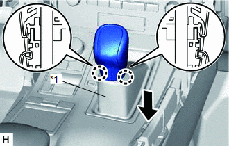
| *1 | Shifting Hole Cover Sub-assembly |
HINT:
Do not rotate the shift lever knob sub-assembly. Pull down the shifting hole cover sub-assembly along the knob axis shown in the illustration.
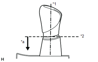
| *1 | Knob Axis |
| *2 | Separation |
| *a | Downward direction to pull shifting hole cover sub-assembly |
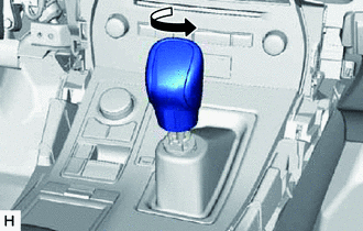
| (b) Twist the shift lever knob sub-assembly in the direction indicated by the arrow and remove it. |
|
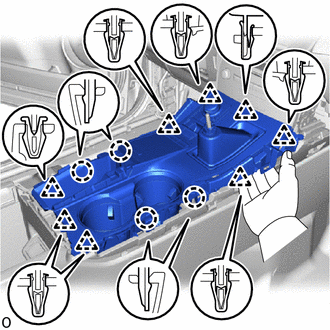
16. REMOVE UPPER REAR CONSOLE PANEL SUB-ASSEMBLY
| (a) Place your hand as shown in the illustration and detach the 4 claws and 8 clips. |
|
(b) Disconnect the connectors and detach the clamp and remove the upper rear console panel sub-assembly.
17. REMOVE INNER NO. 1 INSTRUMENT PANEL BRACE COVER LH
(a) Put protective tape around the inner No. 1 instrument panel brace cover LH.
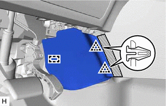
 | Protective Tape |
(b) Detach the 2 clips and guide and remove the inner No. 1 instrument panel brace cover LH.
18. REMOVE INNER NO. 1 INSTRUMENT PANEL BRACE COVER RH
(a) Put protective tape around the inner No. 1 instrument panel brace cover RH.
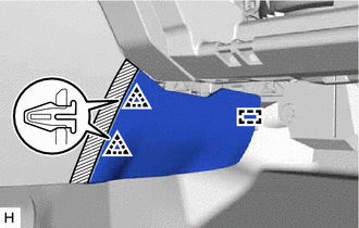
| | Protective Tape |
(b) Detach the 2 clips and guide and remove the inner No. 1 instrument panel brace cover RH.
19. REMOVE REAR CONSOLE END PANEL SUB-ASSEMBLY
(a) Put protective tape around the rear console end panel sub-assembly.
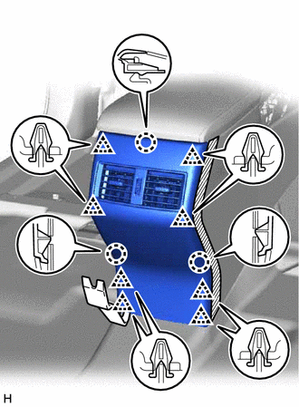
| | Protective Tape |
(b) Using moulding remover B, detach the 8 clips and 3 claws.
(c) Disconnect the connectors and remove the rear console end panel sub-assembly.
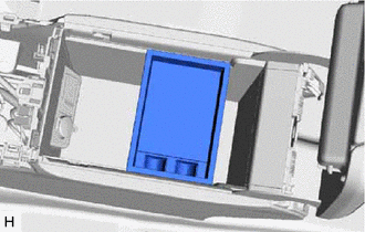
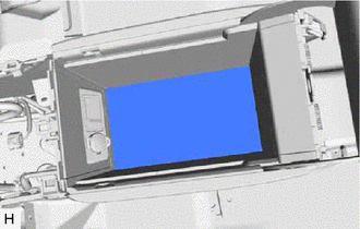
20. REMOVE CONSOLE BOX POCKET (w/o Wireless Charger)
| (a) Remove the console box pocket. |
|
21. REMOVE CONSOLE BOX CARPET
| (a) Remove the console box carpet. |
|
22. REMOVE CONSOLE BOX ASSEMBLY
(a) Disconnect the connectors and detach the clamps.
(b) Remove the 6 bolts.
(c) Detach the 4 guides and remove the console box assembly.
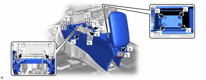
| *a | Connector | *b | Clamp |
| *c | Bolt | *d | Guide |
READ NEXT:
 Disassembly
DISASSEMBLY PROCEDURE 1. REMOVE CONSOLE COMPARTMENT DOOR SUB-ASSEMBLY (a) Remove the 4 screws and console compartment door sub-assembly. 2. REMOVE NO. 3 BOX PANEL (a) Detach the 2 cl
Installation
INSTALLATION CAUTION / NOTICE / HINT HINT: A bolt without a torque specification is shown in the standard bolt chart. Click here PROCEDURE 1. INSTALL CONSOLE BOX ASSEMBLY (a) Attach the 4 guides to
SEE MORE:
Rear Seat Belt Warning Light Malfunction
DESCRIPTION The main body ECU (multiplex network body ECU) detects whether either rear door is open or closed based on the condition of the left and right courtesy light switches and then sends the rear door status signal to the combination meter assembly. The combination meter assembly detects the
Parts Location
PARTS LOCATION ILLUSTRATION *A w/ Memory *B for Triple Beam Headlight *1 OUTER REAR VIEW MIRROR ASSEMBLY RH - SIDE TURN SIGNAL LIGHT ASSEMBLY RH *2 OUTER REAR VIEW MIRROR ASSEMBLY LH - SIDE TURN SIGNAL LIGHT ASSEMBLY LH *3 OUTER MIRROR CONTROL ECU ASSEMBLY RH *4 OUTER M
