Lexus NX: Removal
REMOVAL
PROCEDURE
1. REMOVE DECK BOARD ASSEMBLY
Click here .gif)
2. REMOVE NO. 3 DECK BOARD SUB-ASSEMBLY
Click here
3. REMOVE REAR DECK FLOOR BOX
Click here
4. REMOVE DECK FLOOR BOX LH
Click here
5. PRECAUTION
CAUTION:
Be sure to read Precaution thoroughly before serving.
Click here
NOTICE:
After turning the power switch off, there may be a waiting time before disconnecting the negative (-) auxiliary battery terminal.
Click here
6. DISCONNECT CABLE FROM NEGATIVE AUXILIARY BATTERY TERMINAL
CAUTION:
- Wait at least 90 seconds after disconnecting the cable from the negative (-) auxiliary battery terminal to disable the SRS system.
- If the airbag deploys for any reason. it may cause a serious accident.
7. REMOVE INSTRUMENT PANEL FINISH PLATE
Click here
8. REMOVE MULTI-DISPLAY ASSEMBLY WITH BRACKET
Click here
9. REMOVE CONSOLE ARMREST ASSEMBLY
Click here
10. REMOVE UPPER REAR CONSOLE PANEL
Click here
11. REMOVE UPPER NO. 1 CONSOLE PANEL GARNISH
Click here
12. REMOVE UPPER NO. 2 CONSOLE PANEL GARNISH
Click here
13. REMOVE INSTRUMENT SIDE PANEL RH
Click here
14. REMOVE INSTRUMENT SIDE PANEL LH
Click here
15. REMOVE NO. 1 INSTRUMENT PANEL SAFETY PAD SUB-ASSEMBLY
Click here
16. REMOVE NO. 1 INSTRUMENT PANEL UNDER COVER SUB-ASSEMBLY
Click here
17. REMOVE LOWER NO. 1 INSTRUMENT PANEL FINISH PANEL
Click here
18. REMOVE NO. 1 SWITCH HOLE BASE
Click here
19. REMOVE NO. 2 INSTRUMENT PANEL SAFETY PAD SUB-ASSEMBLY
Click here
20. REMOVE CENTER INSTRUMENT CLUSTER FINISH PANEL ASSEMBLY
Click here
21. REMOVE SHIFT LEVER KNOB SUB-ASSEMBLY
Click here
22. REMOVE UPPER REAR CONSOLE PANEL SUB-ASSEMBLY
Click here
23. REMOVE SHIFT LEVER ASSEMBLY
Click here
24. REMOVE NO. 1 INDOOR ELECTRICAL KEY ANTENNA ASSEMBLY
NOTICE:
Do not reuse dropped or damaged parts.
| (a) Disconnect the connector. |
|
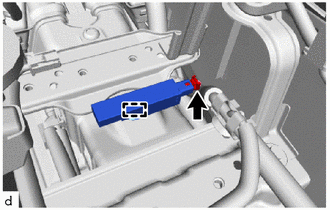
(b) Detach the clamp and remove the No. 1 indoor electrical key antenna assembly.
READ NEXT:
 Installation
INSTALLATION PROCEDURE 1. INSTALL NO. 1 INDOOR ELECTRICAL KEY ANTENNA ASSEMBLY NOTICE: Do not reuse dropped or damaged parts. (a) Attach the clamp and install No. 1 indoor electrical key antenna assem
Components
COMPONENTS ILLUSTRATION *1 TONNEAU COVER ASSEMBLY - - ILLUSTRATION *1 DECK BOARD ASSEMBLY *2 DECK FLOOR BOX LH *3 DECK FLOOR BOX RH - - ILLUSTRATION *1 DECK F
SEE MORE:
Internal Control Module Software Incompatibility Not Programmed (U030051,U030057)
DESCRIPTION
When the forward recognition camera is unable to determine the vehicle information from the vehicle information sent from the hybrid vehicle control ECU, the forward recognition camera outputs U030051.
When the vehicle information sent from the hybrid vehicle control ECU does not ma
Lost Communication with Brake System Control Module (U0129,U0140,U0293)
DESCRIPTION These DTCs are stored when the CAN communication system is malfunctioning. DTC No. Detection Item DTC Detection Condition Trouble Area U0129 Lost Communication with Brake System Control Module The vehicle approaching speaker controller does not receive data from the skid
