Lexus NX: Removal
REMOVAL
PROCEDURE
1. REMOVE UPPER INSTRUMENT PANEL SUB-ASSEMBLY
Click here .gif)
2. REMOVE NO. 1 HEATER TO REGISTER DUCT SUB-ASSEMBLY
Click here
3. REMOVE NAVIGATION ANTENNA ASSEMBLY WITH BRACKET
| (a) Detach the 2 clamps. |
|
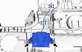
(b) Remove the 2 screws and navigation antenna assembly with bracket.
4. REMOVE ANTENNA CORD SUB-ASSEMBLY
| (a) Detach the 4 claws. |
|
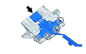
(b) Disconnect the connector and remove the antenna cord sub-assembly.
5. REMOVE NAVIGATION ANTENNA BRACKET
| (a) Detach the 2 claws. |
|
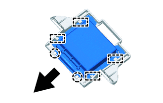
(b) Detach the 4 guides and remove the navigation antenna assembly as shown in the illustration.
6. REMOVE NAVIGATION ANTENNA ASSEMBLY
READ NEXT:
 Inspection
INSPECTION PROCEDURE 1. INSPECT NAVIGATION ANTENNA ASSEMBLY (a) Measure the resistance according to the value(s) in the table below. Standard Resistance: Tester Antenna Tester Connection Co
Installation
INSTALLATION PROCEDURE 1. INSTALL NAVIGATION ANTENNA ASSEMBLY 2. INSTALL NAVIGATION ANTENNA BRACKET (a) Attach the 4 guides to install the navigation antenna assembly as shown in the illustration.
Navigation Ecu
ComponentsCOMPONENTS ILLUSTRATION *1 NAVIGATION ECU *2 NO. 1 RADIO BRACKET *3 NO. 2 RADIO BRACKET *4 RADIO RECEIVER ASSEMBLY WITH BRACKET *5 NAVIGATION WIRE - - Remo
SEE MORE:
Removal
REMOVAL PROCEDURE 1. REMOVE DECK BOARD ASSEMBLY Click here 2. REMOVE NO. 3 DECK BOARD SUB-ASSEMBLY Click here 3. REMOVE REAR DECK FLOOR BOX (w/ Spare Tire) Click here 4. REMOVE DECK FLOOR BOX LH (w/ Spare Tire) Click here 5. PRECAUTION CAUTION: Be sure to read Precaution thoroughly before se
Generator Inverter Performance (P0A7A-122)
DTC SUMMARY MALFUNCTION DESCRIPTION This DTC indicates that a large current flowed in the inverter for the generator. The cause of this malfunction may be one of the following: Area Main Malfunction Description Step Inverter low-voltage circuit The connectors are not connected properly
© 2016-2024 Copyright www.lexunx.com
