Lexus NX: Vehicle Speed Sensor Malfunction (B2415)
Lexus NX Service Manual / Vehicle Exterior / Lighting (ext) / Automatic Headlight Beam Level Control System (for Triple Beam Headlight) / Vehicle Speed Sensor Malfunction (B2415)
DESCRIPTION
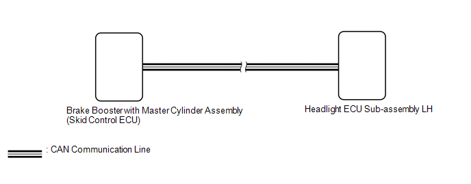
The headlight ECU sub-assembly LH receives speed signals from the brake booster with master cylinder assembly (skid control ECU) via CAN communication and performs light control.
| DTC No. | Detection Item | DTC Detection Condition | Trouble Area |
|---|---|---|---|
| B2415 | Vehicle Speed Sensor Malfunction |
| Electronically controlled brake system |
WIRING DIAGRAM
PROCEDURE
| 1. | CHECK FOR DTC |
(a) Clear the DTCs.
Click here .gif)
(b) Turn the power switch on (IG) and wait for at least 10 seconds or more.
(c) Check for DTCs.
Click here
OK:
DTC B2415 is not output.
| OK | .gif) | USE SIMULATION METHOD TO CHECK |
| NG | | GO TO ELECTRONICALLY CONTROLLED BRAKE SYSTEM |
READ NEXT:
 Height Control Sensor Malfunction (B2416,B241A)
DESCRIPTION The headlight ECU sub-assembly LH supplies 5 V to the rear height control sensor LH, reads changes in the voltage that occur due to height sensor resistance changes according to the vehicl
Headlight Beam Level Control Motor LH Malfunction (B2417,B2418)
DESCRIPTION DTC No. Detection Item DTC Detection Condition Trouble Area B2417 Headlight Beam Level Control Motor LH Malfunction
Power switch on (IG)
Malfunction in headlight
Headlight Leveling Motor LH Communication Malfunction (B2424,B2410,B2411,B2425)
DESCRIPTION Each headlight ECU sub-assembly and headlight swivel and leveling motor communicate via LIN communication. The headlight swivel and leveling motor operates according to power supplied and
SEE MORE:
Power Back Door cannot be Opened or Closed Using the Power Back Door Switch
DESCRIPTION When the power back door cannot be opened or closed using the combination switch assembly, one of the following may be malfunctioning: 1) combination switch assembly circuit, 2) multiplex network door ECU or 3) main body ECU (multiplex network body ECU). WIRING DIAGRAM CAUTION / NOTICE
Components
COMPONENTS ILLUSTRATION *1 DECK FLOOR BOX LH *2 NO. 3 DECK BOARD SUB-ASSEMBLY *3 REAR DECK FLOOR BOX *4 NEGATIVE AUXILIARY BATTERY TERMINAL N*m (kgf*cm, ft.*lbf): Specified torque - - ILLUSTRATION *1 FRONT FLEXIBLE HOSE *2 UNON BOLT *3 GASKET - -
© 2016-2024 Copyright www.lexunx.com
