Lexus NX: Installation
INSTALLATION
PROCEDURE
1. INSTALL NO. 4 ANTENNA CORD SUB-ASSEMBLY
(a) Attach the 2 clamps and guide to install the No. 4 antenna cord sub-assembly.
(b) Install the bolt and attach the 2 clamps to install the washer hose.
(c) Connect each connector.
2. INSTALL NO. 2 ANTENNA CORD SUB-ASSEMBLY
(a) When double-sided tape cannot be reused:
(1) Remove the old double-sided tape
(2) Remove the peeling paper on one side trying not to touch the adhesional surface, and attach new double-sided tape to the position indicated in the illustration
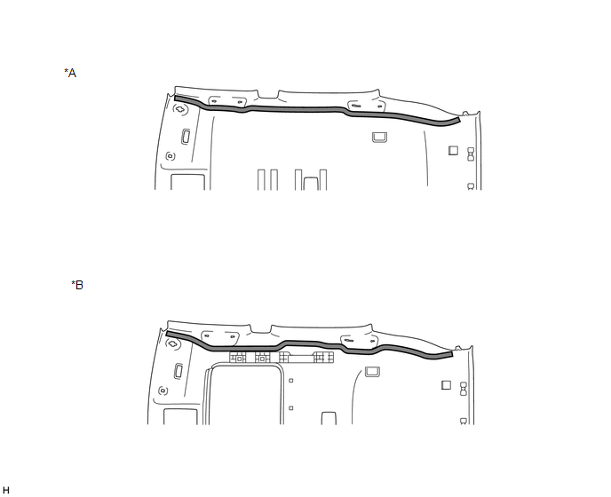
| *A | Normal roof | *B | Sliding roof |
 | Double-sided Tape | - | - |
NOTICE:
Attach securely so that the double-sided tape will not shift or peel off
(3) Remove the peeling paper of the double-sided tape trying not to touch the adhesional surface.
(b) Normal roof
(1) Install the No. 2 antenna cord sub-assembly with the tape aligned to each marking of the roof headlining assembly as shown in the illustration.
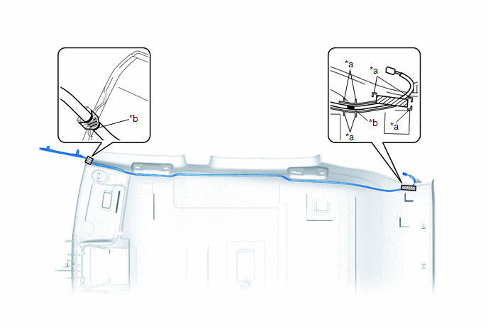
| *a | Marking | *b | Positioning Tape |
.png) | Tape | - | - |
HINT:
- Secure the surplus of the No. 2 antenna cord sub-assembly at the <A> area of the illustration.
- Secure the front part of the No. 2 antenna cord sub-assembly aligning the edge of the positioning tape and tab section of the roof headlining assembly.
- Secure the rear part of the No. 2 antenna cord sub-assembly aligning the edge of the positioning tape and marking of the roof headlining assembly.
(c) Sliding roof
(1) Install the No. 2 antenna cord sub-assembly with the tape aligned to each marking of the roof headlining assembly as shown in the illustration
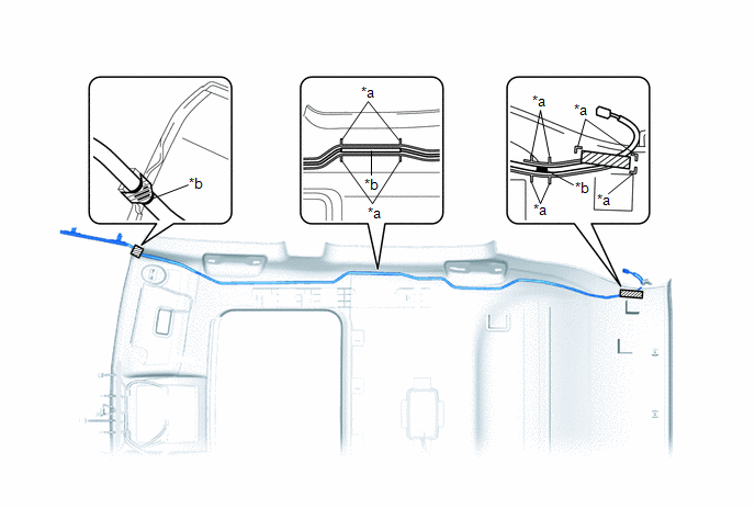
| *a | Marking | *b | Positioning Tape |
| | Tape | - | - |
HINT:
- Secure the surplus of the No. 2 antenna cord sub-assembly at the <A> area of the illustration.
- Secure the front part of the No. 2 antenna cord sub-assembly aligning the edge of the positioning tape and tab section of the roof headlining assembly.
- Secure the rear part of the No. 2 antenna cord sub-assembly aligning the edge of the positioning tape and marking of the roof headlining assembly.
3. INSTALL ROOF HEADLINING ASSEMBLY
Click here .gif)
4. INSTALL NO. 1 ANTENNA CORD SUB-ASSEMBLY
(a) for Type A:
(1) Attach the 7 clamps and guide.
(2) Install the No. 1 antenna cord sub-assembly with the bolt.
Torque:
7.5 N·m {76 kgf·cm, 66 in·lbf}
(3) Connect the 2 connectors.
(b) for Type B:
(1) Attach the 6 clamps and guide.
(2) Install the No. 1 antenna cord sub-assembly with the bolt.
Torque:
7.5 N·m {76 kgf·cm, 66 in·lbf}
(3) Connect the connector.
5. INSTALL UPPER INSTRUMENT PANEL SUB-ASSEMBLY
Click here
6. CONNECT CABLE TO NEGATIVE AUXILIARY BATTERY TERMINAL
7. INITIALIZATION AFTER RECONNECTING AUXILIARY BATTERY TERMINAL
Click here
HINT:
When disconnecting and reconnecting the auxiliary battery, there is an automatic learning function that completes learning when the respective system is used.
Click here
8. CHECK SRS WARNING LIGHT
Click here
READ NEXT:
 Components
COMPONENTS ILLUSTRATION *1 DECK FLOOR BOX LH *2 NO. 3 DECK BOARD SUB-ASSEMBLY *3 REAR DECK FLOOR BOX *4 NEGATIVE AUXILIARY BATTERY TERMINAL N*m (kgf*cm, ft.*lbf): Specified
Removal
REMOVAL PROCEDURE 1. REMOVE DECK BOARD ASSEMBLY Click here 2. REMOVE NO. 3 DECK BOARD SUB-ASSEMBLY Click here 3. REMOVE REAR DECK FLOOR BOX Click here 4. REMOVE DECK FLOOR BOX LH Click here 5.
SEE MORE:
Brake Hydraulic Pressure Malfunction (C164F)
DESCRIPTION When a malfunction signal sent from the brake booster with master cylinder assembly (skid control ECU) via CAN communication is detected by the clearance warning ECU assembly, DTC C164F is stored. DTC No. Detection Item DTC Detection Condition Trouble Area C164F Brake Hydr
CD/DVD Sound Skips
CAUTION / NOTICE / HINT NOTICE: When replacing the radio receiver assembly, always replace it with a new one. If a radio receiver assembly which was installed to another vehicle is used, the following may occur:
A communication malfunction DTC may be stored.
The radio receiver assembly may not
