- Short to +B in CAN main bus wire
- Short to +B in CAN branch wire
- Forward recognition camera*1
- Clearance warning ECU assembly*2
- Millimeter wave Radar sensor assembly*1
- Central gateway ECU (network gateway ECU)
- Parking assist ECU*3
- Blind spot monitor sensor LH*4
- Rear television camera assembly
- Hybrid vehicle control ECU
- Absorber control ECU*5
- Vehicle approaching speaker controller
- No. 4 CAN junction connector
- No. 7 CAN junction connector
Lexus NX: Check Bus 5 Line for Short to +B
Lexus NX Service Manual / Power Source & Network / Networking / Can Communication System / Check Bus 5 Line for Short to +B
DESCRIPTION
There may be a short circuit between one of the CAN bus lines and +B when there is no resistance between terminal 15 (CA5H) of the central gateway ECU (network gateway ECU) and terminal 16 (BAT) of the DLC3, or terminal 16 (CA5L) of the central gateway ECU (network gateway ECU) and terminal 16 (BAT) of the DLC3.
| Symptom | Trouble Area |
|---|---|
|
*1: w/ Pre-collision System
*2: w/ Intuitive Parking Assist System *3: w/ Panoramic View Monitor System *4: w/ Blind Spot Monitor System *5: w/ Adaptive Variable Suspension System | |
| There is no resistance between terminal 15 (CA5H) of the central gateway ECU (network gateway ECU) and terminal 16 (BAT) of the DLC3, or terminal 16 (CA5L) of the central gateway ECU (network gateway ECU) and terminal 16 (BAT) of the DLC3. | |
WIRING DIAGRAM
.png)
CAUTION / NOTICE / HINT
CAUTION:
When performing the confirmation driving pattern, obey all speed limits and traffic laws.
NOTICE:
- Inspect the fuses for circuits related to this system before performing the following procedure.
- Before measuring the resistance of the CAN bus, turn the power switch off and leave the vehicle for 1 minute or more without operating the key or any switches, or opening or closing the doors. After that, disconnect the cable from the negative (-) auxiliary battery terminal and leave the vehicle for 1 minute or more before measuring the resistance.
-
After turning the power switch off, waiting time may be required before disconnecting the cable from the negative (-) auxiliary battery terminal.
Click here
.gif)
-
When disconnecting and reconnecting the auxiliary battery.
Click here
HINT:
When disconnecting and reconnecting the auxiliary battery, there is an automatic learning function that completes learning when the respective system is used.
Click here
-
Some parts must be initialized and set when replacing or removing and installing parts.
Click here
-
Because the order of diagnosis is important to allow correct diagnosis, make sure to begin troubleshooting using How to Proceed with Troubleshooting when CAN communication system related DTCs are output.
Click here
-
After performing repairs, perform the DTC check procedure and confirm that the DTCs are not output again.
DTC check procedure: Turn the power switch on (IG) and wait for 1 minute or more. Then operate the suspected malfunctioning system and drive the vehicle at 60 km/h (37 mph) or more for 5 minutes or more.
-
After the repair, perform the CAN bus check and check that all the ECUs and sensors connected to the CAN communication system are displayed as normal.
Click here
HINT:
- Operating the power switch, any switches or any doors triggers related ECU and sensor communication with the CAN, which causes resistance variation.
- Even after DTCs are cleared, if a DTC is stored again after driving the vehicle for a while, the malfunction may be occurring due to vibration of the vehicle. In such a case, wiggling the ECUs or wire harness while performing the inspection below may help determine the cause of the malfunction.
PROCEDURE
| 1. | CHECK FOR SHORT TO B+ IN CAN BUS WIRE (NO. 4 CAN JUNCTION CONNECTOR) |
(a) Disconnect the cable from the negative (-) auxiliary battery terminal.
(b) Disconnect the No. 4 CAN junction connector.
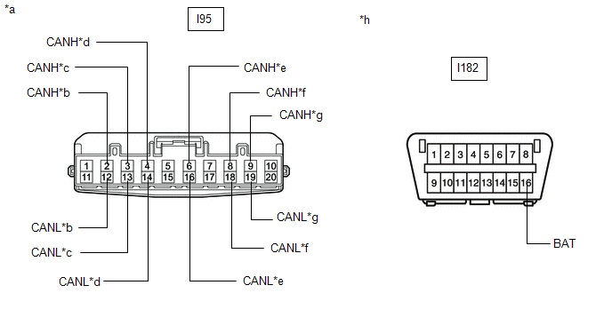
| *a | Front view of wire harness connector (to No. 4 CAN Junction Connector) | *b | to Vehicle Approaching Speaker Controller |
| *c | to Central Gateway ECU (Network Gateway ECU) | *d | to Millimeter Wave Radar Sensor Assembly (w/ Pre-collision System) |
| *e | to Clearance Warning ECU Assembly (w/ Intuitive Parking Assist System) | *f | to Forward Recognition Camera (w/ Pre-collision System) |
| *g | to No. 7 CAN Junction Connector | *h | Front view of DLC3 |
(c) Measure the resistance according to the value(s) in the table below.
Standard Resistance:
| Tester Connection | Condition | Specified Condition | Connected to |
|---|---|---|---|
|
*1: w/ Pre-collision System
*2: w/ Intuitive Parking Assist System | |||
| I95-2 (CANH) - I182-16 (BAT) | Cable disconnected from negative (-) auxiliary battery terminal | 6 kΩ or higher | Vehicle approaching speaker controller |
| I95-12 (CANL) - I182-16 (BAT) | |||
| I95-3 (CANH) - I182-16 (BAT) | Cable disconnected from negative (-) auxiliary battery terminal | 6 kΩ or higher | Central gateway ECU (network gateway ECU) |
| I95-13 (CANL) - I182-16 (BAT) | |||
| I95-4 (CANH) - I182-16 (BAT) | Cable disconnected from negative (-) auxiliary battery terminal | 6 kΩ or higher | Millimeter wave radar sensor assembly*1 |
| I95-14 (CANL) - I182-16 (BAT) | |||
| I95-6 (CANH) - I182-16 (BAT) | Cable disconnected from negative (-) auxiliary battery terminal | 6 kΩ or higher | Clearance warning ECU assembly*2 |
| I95-16 (CANL) - I182-16 (BAT) | |||
| I95-8 (CANH) - I182-16 (BAT) | Cable disconnected from negative (-) auxiliary battery terminal | 6 kΩ or higher | Forward recognition camera*1 |
| I95-18 (CANL) - I182-16 (BAT) | |||
| I95-9 (CANH) - I182-16 (BAT) | Cable disconnected from negative (-) auxiliary battery terminal | 6 kΩ or higher | No. 7 CAN junction connector |
| I95-19 (CANL) - I182-16 (BAT) | |||
| Result | Proceed to |
|---|---|
| OK | A |
| NG (Central gateway ECU [network gateway ECU] main wire) | B |
| NG (No. 7 CAN junction connector CAN main wire) | C |
| NG (Wire to ECU or sensor) | D |
| A | .gif) | REPLACE NO. 4 CAN JUNCTION CONNECTOR |
| C | | GO TO STEP 4 |
| D | | GO TO STEP 6 |
|
.gif)
| 2. | CONNECT CONNECTOR |
(a) Reconnect the I95 No. 4 CAN junction connector.
|
| 3. | CHECK FOR SHORT TO B+ IN CAN BUS WIRE (CENTRAL GATEWAY ECU [NETWORK GATEWAY ECU] - NO. 4 CAN JUNCTION CONNECTOR) |
(a) Disconnect the central gateway ECU (network gateway ECU) connector.
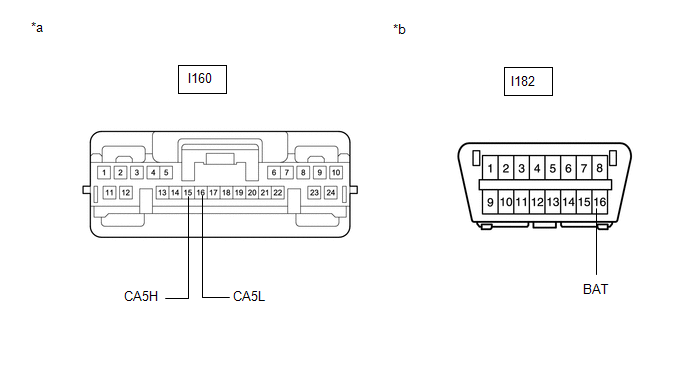
| *a | Front view of wire harness connector (to Central Gateway ECU [Network Gateway ECU]) | *b | Front view of DLC3 |
(b) Measure the resistance according to the value(s) in the table below.
Standard Resistance:
| Tester Connection | Condition | Specified Condition |
|---|---|---|
| I160-15 (CA5H) - I182-16 (BAT) | Cable disconnected from negative (-) auxiliary battery terminal | 6 kΩ or higher |
| I160-16 (CA5L) - I182-16 (BAT) |
| OK | | REPLACE CENTRAL GATEWAY ECU (NETWORK GATEWAY ECU) |
| NG | | REPAIR OR REPLACE CAN MAIN WIRE OR CONNECTOR (CENTRAL GATEWAY ECU [NETWORK GATEWAY ECU] - NO. 4 CAN JUNCTION CONNECTOR) |
| 4. | CONNECT CONNECTOR |
(a) Reconnect the I95 No. 4 CAN junction connector.
|
| 5. | CHECK FOR SHORT TO B+ IN CAN BUS WIRE (NO. 7 CAN JUNCTION CONNECTOR) |
(a) Disconnect the No. 7 CAN junction connector.
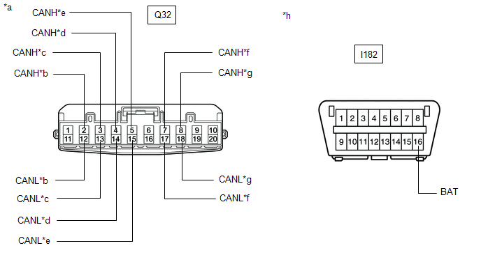
| *a | Front view of wire harness connector (to No. 7 CAN Junction Connector) | *b | to Parking Assist ECU (w/ Panoramic View Monitor System) |
| *c | to Blind Spot Monitor Sensor LH (w/ Blind Spot Monitor System) | *d | to Hybrid Vehicle Control ECU |
| *e | to No. 4 CAN Junction Connector | *f | to Absorber Control ECU (w/ Adaptive Variable Suspension System) |
| *g | to Rear Television Camera Assembly | *h | Front view of DLC3 |
(b) Measure the resistance according to the value(s) in the table below.
Standard Resistance:
| Tester Connection | Condition | Specified Condition | Connected to |
|---|---|---|---|
|
*1: w/ Panoramic View Monitor System
*2: w/ Blind Spot Monitor System *3: w/ Adaptive Variable Suspension System | |||
| Q32-2 (CANH) - I182-16 (BAT) | Cable disconnected from negative (-) auxiliary battery terminal | 6 kΩ or higher | Parking assist ECU*1 |
| Q32-12 (CANL) - I182-16 (BAT) | |||
| Q32-3 (CANH) - I182-16 (BAT) | Cable disconnected from negative (-) auxiliary battery terminal | 6 kΩ or higher | Blind spot monitor sensor LH*2 |
| Q32-13 (CANL) - I182-16 (BAT) | |||
| Q32-4 (CANH) - I182-16 (BAT) | Cable disconnected from negative (-) auxiliary battery terminal | 6 kΩ or higher | Hybrid Vehicle Control ECU |
| Q32-14 (CANL) - I182-16 (BAT) | |||
| Q32-5 (CANH) - I182-16 (BAT) | Cable disconnected from negative (-) auxiliary battery terminal | 6 kΩ or higher | No. 4 CAN junction connector |
| Q32-15 (CANL) - I182-16 (BAT) | |||
| Q32-7 (CANH) - I182-16 (BAT) | Cable disconnected from negative (-) auxiliary battery terminal | 6 kΩ or higher | Absorber control ECU*3 |
| Q32-17 (CANL) - I182-16 (BAT) | |||
| Q32-8 (CANH) - I182-16 (BAT) | Cable disconnected from negative (-) auxiliary battery terminal | 6 kΩ or higher | Rear television camera assembly |
| Q32-18 (CANL) - I182-16 (BAT) | |||
| Result | Proceed to |
|---|---|
| OK | A |
| NG (No. 4 CAN junction connector CAN main wire) | B |
| NG (Wire to ECU or sensor) | C |
| A | | REPLACE NO. 7 CAN JUNCTION CONNECTOR |
| B | | REPAIR OR REPLACE CAN MAIN WIRE OR CONNECTOR (NO. 7 CAN JUNCTION CONNECTOR - NO. 4 CAN JUNCTION CONNECTOR) |
| C | | GO TO STEP 6 |
| 6. | CHECK FOR SHORT TO B+ IN CAN BUS WIRE (ECU, SENSOR) |
(a) Reconnect all wire harness connectors.
(b) Disconnect the connector that includes terminals CANH and CANL from the ECU or sensor to which the bus line shorted to +B is connected.
Click here
(c) Measure the resistance according to the value(s) in the table below.
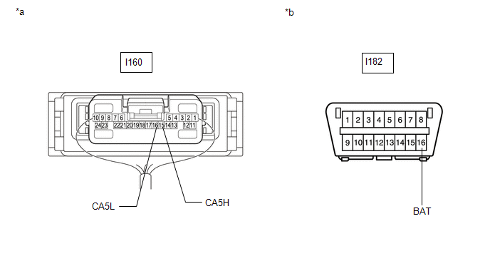
| *a | Component with harness connected (Central Gateway ECU [Network Gateway ECU]) | *b | Front view of DLC3 |
Standard Resistance:
| Tester Connection | Condition | Specified Condition |
|---|---|---|
| I160-15 (CA5H) - I182-16 (BAT) | Cable disconnected from negative (-) auxiliary battery terminal | 6 kΩ or higher |
| I160-16 (CA5L) - I182-16 (BAT) |
HINT:
If the resistance changes to 6 kΩ or higher when the connector is disconnected from the ECU or sensor, there may be a short in the ECU or sensor.
| OK | | REPLACE ECU OR SENSOR |
| NG | | REPAIR OR REPLACE HARNESS OR CONNECTOR |
READ NEXT:
 Check Bus 5 Line for Short to GND
DESCRIPTION There may be a short circuit between one of the CAN bus lines and GND when there is no resistance between terminal 15 (CA5H) of the central gateway ECU (network gateway ECU) and terminal 4
Open in One Side of Bus 5 Branch Line
DESCRIPTION When the CAN bus main lines are normal (no open, short to ground, short to +B or short between lines) and there is an ECU or sensor on the "Communication Bus Check" screen that is indicate
Front Camera Module Communication Stop Mode
DESCRIPTION Detection Item Symptom Trouble Area Front Camera Module Communication Stop Mode Any of the following conditions are met:
Communication stop for "Front Camera Module" is ind
SEE MORE:
Sleep Operation Failure of Occupant Classification ECU (B1796)
DESCRIPTION During sleep mode, the occupant detection ECU monitors the condition of each sensor while the power switch is off. In this mode, if the occupant detection ECU detects an internal malfunction, DTC B1796 is stored. DTC No. Detection Item DTC Detection Condition Trouble Area B1
Hazard Warning Switch Circuit
DESCRIPTION When the combination meter receives a hazard warning signal switch signal, the flasher IC turns on and hazard control is performed. WIRING DIAGRAM CAUTION / NOTICE / HINT NOTICE: When replacing the combination meter assembly, make sure to replace it with a new one. PROCEDURE 1. RE
© 2016-2026 Copyright www.lexunx.com
