Lexus NX: Installation
INSTALLATION
CAUTION / NOTICE / HINT
NOTICE:
- When the brake pedal is first depressed after replacing the brake pads or pushing back the disc brake piston, DTC C1214 may be output. As there is no malfunction, clear the DTC.
- While the auxiliary battery is connected, even if the power switch is off, the brake control system activates when the brake pedal is depressed or the door courtesy switch is turned on. Therefore, even if only brake shoes are to be removed and installed, be sure to perform the Disable Brake Control procedure and disconnect the cable from the negative (-) terminal of the auxiliary battery before beginning work.
HINT:
- Use the same procedure for the RH and LH sides.
- The procedure listed below is for the LH side.
PROCEDURE
1. INSTALL FRONT AXLE HUB SUB-ASSEMBLY LH
(a) Secure the steering knuckle in a vise.
NOTICE:
When using a vise, do not overtighten it.
(b) Install the front brake dust cover to the steering knuckle.
(c) Install the front axle hub sub-assembly with the 4 bolts.
Torque:
96 N·m {979 kgf·cm, 71 ft·lbf}
NOTICE:
Do not place the hub and bearing's magnet rotor side so that it is facing downward, and do not allow the magnet rotor side to become damaged or contact foreign matter.
2. INSTALL FRONT AXLE ASSEMBLY LH
| (a) Align the matchmarks and install the front drive shaft assembly to the front axle hub sub-assembly. |
|
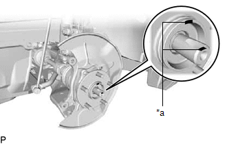
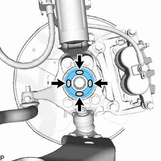
| (b) Apply MP grease to the entire contact surface between the front drive shaft assembly and axle hub bearing surface or only apply 0.1 to 0.3 g (0.00353 to 0.0105 oz.) of MP grease to the 4 areas on the axle hub bearing shown in the illustration. |
|
(c) Install the front axle assembly to the front shock absorber assembly with coil spring with the 2 bolts and 2 nuts.
Torque:
240 N·m {2447 kgf·cm, 177 ft·lbf}
NOTICE:
Be careful not to damage the drive shaft boot and speed sensor rotor.
NOTICE:
- Be careful not to damage the drive shaft boot and speed sensor rotor.
- Do not tighten the bolts.
3. CONNECT FRONT LOWER NO. 1 SUSPENSION ARM SUB-ASSEMBLY LH
(a) Connect the front lower No. 1 suspension arm sub-assembly to the lower arm ball joint with the bolt and 2 nuts.
Torque:
92 N·m {938 kgf·cm, 68 ft·lbf}
4. CONNECT TIE ROD END SUB-ASSEMBLY LH
Click here .gif)
5. INSTALL FRONT DISC
Click here
6. CONNECT FRONT DISC BRAKE CALIPER ASSEMBLY LH
(a) Connect the front disc brake caliper assembly to the steering knuckle with the 2 bolts.
Torque:
106.8 N·m {1089 kgf·cm, 79 ft·lbf}
7. TEMPORARILY INSTALL FRONT AXLE SHAFT NUT LH
(a) Clean the threaded parts on the drive shaft and a new axle shaft nut using a non-residue solvent.
NOTICE:
- Be sure to perform this work for a new drive shaft.
- Keep the threaded parts free of oil and foreign objects.
(b) Using a 30 mm socket wrench, temporarily install a new axle shaft nut.
Torque:
292 N·m {2978 kgf·cm, 215 ft·lbf}
HINT:
Stake the nut after inspecting for looseness and runout in the following steps.
8. DISCONNECT FRONT DISC BRAKE CALIPER ASSEMBLY LH
Click here
9. REMOVE FRONT DISC
Click here
10. INSPECT FRONT AXLE HUB BEARING LOOSENESS
Click here
11. INSPECT FRONT AXLE HUB RUNOUT
Click here
12. INSTALL FRONT DISC
Click here
13. CONNECT FRONT DISC BRAKE CALIPER ASSEMBLY LH
(a) Connect the front disc brake caliper assembly to the steering knuckle with the 2 bolts.
Torque:
106.8 N·m {1089 kgf·cm, 79 ft·lbf}
14. CONNECT FRONT FLEXIBLE HOSE (w/o AVS)
(a) Connect the front flexible hose to the steering knuckle with the bolt.
Torque:
18.8 N·m {192 kgf·cm, 14 ft·lbf}
15. CONNECT FRONT SPEED SENSOR LH (w/ AVS)
Click here
16. CONNECT FRONT SPEED SENSOR LH (w/o AVS)
Click here
17. INSTALL FRONT AXLE SHAFT NUT LH
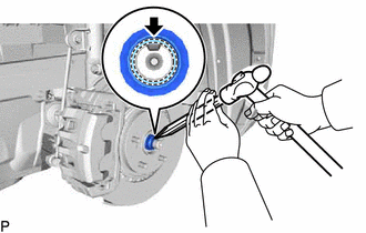
| (a) Using a chisel and hammer, stake the front axle shaft nut. |
|
18. INSTALL FRONT WHEEL
Click here
19. CONNECT CABLE TO NEGATIVE AUXILIARY BATTERY TERMINAL
(a) Connect the cable to the negative (-) auxiliary battery terminal and tighten the nut.
Torque:
5.4 N·m {55 kgf·cm, 48 in·lbf}
20. INSPECT AND ADJUST FRONT WHEEL ALIGNMENT
Click here
21. CHECK FOR SPEED SENSOR SIGNAL
Click here
READ NEXT:
 Components
COMPONENTS ILLUSTRATION *1 FRONT AXLE HUB BOLT LH *2 FRONT DISC *3 FRONT DISC BRAKE CALIPER ASSEMBLY LH - - N*m (kgf*cm, ft.*lbf): Specified torque ● Non-reusable part
Replacement
REPLACEMENT CAUTION / NOTICE / HINT NOTICE:
When the brake pedal is first depressed after replacing the brake pads or pushing back the disc brake piston, DTC C1214 may be output. As there is no mal
SEE MORE:
Precaution
PRECAUTION PRECAUTION FOR DISCONNECTING CABLE FROM NEGATIVE AUXILIARY BATTERY TERMINAL NOTICE: When disconnecting the cable from the negative (-) auxiliary battery terminal, perform steering angle sensor zero point calibration after the cable is reconnected. Click here PRECAUTIONS FOR LANE TRACING
Data List / Active Test
DATA LIST / ACTIVE TEST DATA LIST NOTICE: In the table below, the values listed under "Normal Condition" are reference values. Do not depend solely on these reference values when deciding whether a part is faulty or not. HINT: Using the Techstream to read the Data List allows the values or states of
