Lexus NX: Parts Location
Lexus NX Service Manual / Vehicle Interior / Power Outlets (int) / Wireless Charging System / Parts Location
PARTS LOCATION
ILLUSTRATION
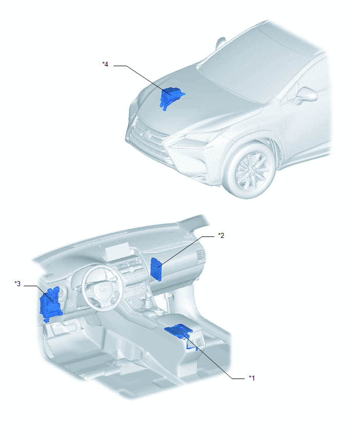
| *1 | MOBILE WIRELESS CHARGER CRADLE ASSEMBLY | *2 | CERTIFICATION ECU (SMART KEY ECU ASSEMBLY) |
| *3 | INSTRUMENT PANEL JUNCTION BLOCK ASSEMBLY - ACC FUSE - PANEL FUSE | *4 | NO. 2 ENGINE ROOM RELAY BLOCK - ECU-B NO.1 FUSE |
READ NEXT:
 Precaution
PRECAUTION HANDLING PRECAUTIONS (a) For safety, when driving the vehicle, the driver should not operate a portable device that is charging. (b) Anyone using an implanted pacemaker, biventricular pacin
System Diagram
SYSTEM DIAGRAM
System Description
SYSTEM DESCRIPTION WIRELESS CHARGING SYSTEM (a) The wireless charging system allows Qi-compatible* devices to be charged without the use of a charging cable by placing them on the charging area of the
SEE MORE:
Terminals Of Ecu
TERMINALS OF ECU CHECK MULTIPLEX NETWORK DOOR ECU (a) Disconnect the Y26 and Y27 multiplex network door ECU connectors. (b) Measure the voltage and resistance according to the value(s) in the table below. Terminal No. (Symbol) Wiring Color Terminal Description Condition Specified Conditi
Components
COMPONENTS ILLUSTRATION *1 ACCELERATION SENSOR *2 COWL SIDE TRIM BOARD LH *3 DOOR SCUFF PLATE ASSEMBLY LH *4 GLOVE COMPARTMENT DOOR ASSEMBLY *5 NO. 1 INSTRUMENT PANEL UNDER COVER SUB-ASSEMBLY *6 CONNECTOR N*m (kgf*cm, ft.*lbf): Specified torque - -
© 2016-2026 Copyright www.lexunx.com
