Lexus NX: System Diagram
SYSTEM DIAGRAM
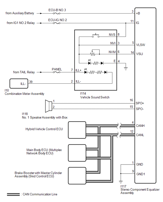 Communication Table
 | Sender | Receiver | Signal | Line |
|---|---|---|---|
| Brake booster with master cylinder assembly (skid control ECU) | Stereo component equalizer assembly | Vehicle speed signal | CAN |
| Hybrid vehicle control ECU | Stereo component equalizer assembly | Engine speed signal | |
| Accelerator pedal angle signal | |||
| Integration sports mode indicator signal | |||
| Shift position P signal | |||
| Shift position R signal | |||
| Shift position D signal | |||
| Shift position N signal | |||
| Sport mode indicator signal | |||
| Shift gear signal | |||
| Engine mode ID signal | |||
| ECO mode indicator signal | |||
| Hybrid vehicle control ECU | |||
| Integration sports mode signal | |||
| Main body ECU (multiplex network body ECU) | Stereo component equalizer assembly | Trip count signal | |
| Time count signal |
READ NEXT:
 System Description
SYSTEM DESCRIPTION ASC SYSTEM (a) The ASC system uses a stereo component equalizer assembly to electronically generate a driving sound. Simulated engine sounds are output from the No. 1 speaker assemb
How To Proceed With Troubleshooting
CAUTION / NOTICE / HINT HINT:
Use the following procedure to troubleshoot the ASC system.
*: Use the Techstream.
PROCEDURE 1. VEHICLE BROUGHT TO WORKSHOP
NEXT 2.
Operation Check
OPERATION CHECK INSPECT ASC SYSTEM OPERATION CAUTION: Check for safety before performing any tests. HINT: When the drive mode changes to a mode other than NORMAL, SPORT or CUSTOMIZE*, the simulated en
SEE MORE:
Internal Control Module EEPROM Error (P062F)
DESCRIPTION The ECM monitors its internal operation and stores this DTC when it detects an internal malfunction. DTC No. Detection Item DTC Detection Condition Trouble Area MIL Memory P062F Internal Control Module EEPROM Error An ECM internal error (EEPROM) (1 trip detection log
Knock Sensor 1 Circuit Low Input (Bank 1 or Single Sensor) (P0327,P0328)
DESCRIPTION A flat type knock control sensor (non-resonant type) has a structure that can detect vibration between approximately 5 kHz and 23 kHz. The knock control sensors are fitted onto the engine block to detect engine knocking. The knock control sensor contains a piezoelectric element which gen
© 2016-2026 Copyright www.lexunx.com
