Lexus NX: Telephone Sub Antenna Circuit Short to Ground (B153711,B153713)
DESCRIPTION
These DTCs are stored when a malfunction occurs in the telephone antenna (navigation antenna assembly)
| DTC No. | Detection Item | DTC Detection Condition | Trouble Area |
|---|---|---|---|
| B153711 | Telephone Sub Antenna Circuit Short to Ground | Telephone antenna (sub) impedance (Ω) is lower than the malfunction threshold for 10 seconds or more when the power switch is on (IG). (Short circuit) |
|
| B153713 | Telephone Sub Antenna Circuit Open | Telephone antenna (sub) impedance (Ω) is higher than the malfunction threshold for 10 seconds or more when the power switch is on (IG). (Open circuit) |
|
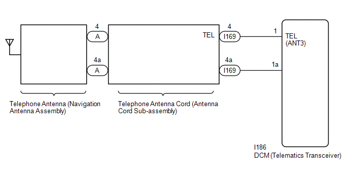
WIRING DIAGRAM
CAUTION / NOTICE / HINT
NOTICE:
Depending on the parts that are replaced during vehicle inspection or maintenance, performing initialization, registration or calibration may be needed. Refer to Precaution for Safety Connect System.
Click here .gif)
HINT:
Refer to "PARTS LOCATION" for the installation location of telephone antenna cord.
Click here
PROCEDURE
| 1. | CHECK DTC |
(a) Turn the power switch off.
(b) Connect the Techstream to the DLC3.
(c) Turn the power switch on (IG) and wait for 10 seconds or more.
(d) Turn the Techstream on.
(e) Check for DTCs and check that no DTCs are output.
Click here
OK:
No DTCs are output.
| OK | .gif) | USE SIMULATION METHOD TO CHECK |
|
.gif)
| 2. | INSPECT TELEPHONE ANTENNA (NAVIGATION ANTENNA ASSEMBLY) |
(a) Remove the telephone antenna (navigation antenna assembly).
Click here
(b) Inspect the telephone antenna (navigation antenna assembly).
Click here
| NG | | REPLACE TELEPHONE ANTENNA (NAVIGATION ANTENNA ASSEMBLY) |
|
| 3. | INSPECT TELEPHONE ANTENNA CORD (ANTENNA CORD SUB-ASSEMBLY) |
| (a) Disconnect the antenna connector from the navigation antenna assembly. |
|
(b) Disconnect the antenna connector from the wire harness.
(c) Measure the resistance according to the value(s) in the table below.
Standard Resistance:
| Tester Connection | Condition | Specified Condition |
|---|---|---|
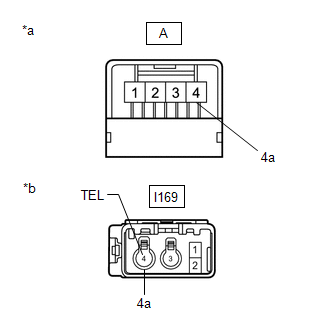
| A-4 - I169-4 (TEL) | Always | Below 1 Ω |
| A-4a - I169-4a | Always | Below 1 Ω |
| A-4 - Body ground | Always | 10 kΩ or higher |
| NG | | REPLACE TELEPHONE ANTENNA CORD (ANTENNA CORD SUB-ASSEMBLY) |
|
| 4. | CHECK HARNESS AND CONNECTOR (ANTENNA CORD SUB-ASSEMBLY - DCM [TELEMATICS TRANSCEIVER]) |
| (a) Disconnect the antenna cord sub-assembly connector. |
|
(b) Disconnect the DCM (telematics transceiver) connector.
(c) Measure the resistance according to the value(s) in the table below.
Standard Resistance:
| Tester Connection | Condition | Specified Condition |
|---|---|---|
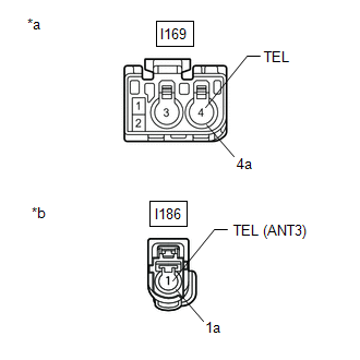
| I169-4 (TEL) - I186-1 (TEL [ANT3]) | Always | Below 1 Ω |
| I169-4a - I169-1a | Always | Below 1 Ω |
| I169-4 (TEL) - Body ground | Always | 10 kΩ or higher |
| NG | | REPAIR OR REPLACE HARNESS OR CONNECTOR |
|
| 5. | CHECK TELEPHONE ANTENNA (NAVIGATION ANTENNA ASSEMBLY) |
(a) Replace the telephone antenna (navigation antenna assembly) with a known good one.
Click here
(b) Clear the DTCs.
Click here
(c) Recheck for DTCs and check that no DTCs are output.
Click here
OK:
No DTCs are output.
| OK | | END (TELEPHONE ANTENNA [NAVIGATION ANTENNA ASSEMBLY] IS DEFECTIVE) |
|
| 6. | REPLACE DCM (TELEMATICS TRANSCEIVER) |
(a) Replace the DCM (telematics transceiver).
Click here
NOTICE:
- The power switch must be off.
- Do not exchange the DCM (telematics transceiver) with one from another vehicle.
| NEXT | | PERFORM DCM ACTIVATION |
READ NEXT:
 DCM System Internal Failure (B15A804)
DESCRIPTION This DTC is stored when an internal circuit malfunction is detected by the DCM (telematics transceiver) self check. DTC No. Detection Item DTC Detection Condition Trouble Area
Telephone Main Antenna Circuit Short to Ground (B15CB11,B15CB13)
DESCRIPTION This DTC is stored when the DCM (telematics transceiver) detects an open or a short in the telephone and GPS antenna (roof antenna assembly) circuit. DTC No. Detection Item DTC Dete
Green Indicator Remains Off
DESCRIPTION After power switch on (IG), the DCM (telematics transceiver) will enter into self check mode. The manual (SOS) switch red indicator will illuminate for 2 seconds and turn off followed by t
SEE MORE:
Installation
INSTALLATION PROCEDURE 1. INSTALL REAR HEADER SPEAKER ASSEMBLY NOTICE: Do not touch the cone part of the speaker. (a) Temporarily install the speaker by attaching the clip of the speaker to the vehicles body. (b) Install the rear header speaker assembly with the bolt. Torque: 7.5 N·
Parts Location
PARTS LOCATION ILLUSTRATION *1 COOLING FAN RELAY (FAN NO. 1) *2 COOLING FAN ECU *3 COOLING FAN MOTOR *4 CRANKSHAFT POSITION SENSOR *5 ECM *6 NO. 2 ENGINE ROOM RELAY BLOCK - FAN FUSE *7 NO. 2 COOLING FAN MOTOR *8 INSTRUMENT PANEL JUNCTION BLOCK - ECU-IG NO. 4 F
