Lexus NX: AVC-LAN Circuit
DESCRIPTION
Each audio system component connected to the AVC-LAN (communication bus) transfers switch signals using the audio visual communication local area network.
If a short to +B or short to ground occurs in the AVC-LAN, the audio system will not function normally because communication is not possible.
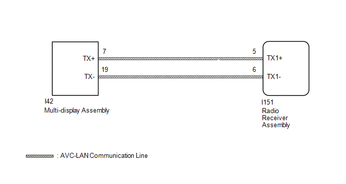
WIRING DIAGRAM
CAUTION / NOTICE / HINT
NOTICE:
When replacing the radio receiver assembly, always replace it with a new one.
If a radio receiver assembly which was installed to another vehicle is used, the following may occur:
- A communication malfunction DTC may be stored.
- The radio receiver assembly may not operate normally.
HINT:
Depending on the parts that are replaced during vehicle inspection or maintenance, performing initialization, registration or calibration may be needed. Refer to Precaution for Navigation System.
Click here .gif)
PROCEDURE
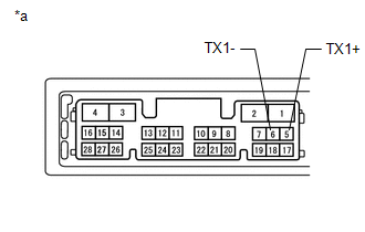
| 1. | INSPECT RADIO RECEIVER ASSEMBLY |
(a) Remove the radio receiver assembly.
Click here
| (b) Measure the resistance according to the value(s) in the table below. Standard Resistance:
|
|
| NG | .gif) | REPLACE RADIO RECEIVER ASSEMBLY |
|
.gif)
| 2. | CHECK HARNESS AND CONNECTOR (AVC-LAN CIRCUIT) |
(a) Disconnect the I151 radio receiver assembly connector.
(b) Disconnect the I42 multi-display assembly connector.
(c) Measure the resistance according to the value(s) in the table below.
Standard Resistance:
| Tester Connection | Condition | Specified Condition |
|---|---|---|
| I151-5 (TX1+) - I42-7 (TX+) | Always | Below 1 Ω |
| I151-6 (TX1-) - I42-19 (TX-) | Always | Below 1 Ω |
| I151-5 (TX1+) - Body ground | Always | 10 kΩ or higher |
| I151-6 (TX1-) - Body ground | Always | 10 kΩ or higher |
| NG | | REPAIR OR REPLACE HARNESS OR CONNECTOR |
|
| 3. | INSPECT MALFUNCTIONING PARTS |
(a) Disconnect and reconnect each slave unit one by one until the master unit returns to normal operation.
HINT:
- Check all slave units.
- When disconnecting a slave unit causes the master unit to return to normal operation, this indicates that the slave unit is malfunctioning. Replace the malfunctioning slave unit.
OK:
Master unit returns to normal operation.
| OK | | REPLACE MALFUNCTIONING PARTS |
| NG | | REPLACE RADIO RECEIVER ASSEMBLY |
READ NEXT:
 Vehicle Speed Signal Circuit between Navigation ECU and Combination Meter
DESCRIPTION The navigation ECU receives a vehicle speed signal from the combination meter assembly. HINT:
A voltage of 12 V or 5 V is output from each ECU and then input to the combination meter as
Vehicle Speed Signal Circuit between Stereo Component Amplifier and Combination Meter
DESCRIPTION The stereo component amplifier assembly receives a vehicle speed signal from the combination meter assembly to control the ASL function. HINT:
A voltage of 12 V or 5 V is output from ea
Reverse Signal Circuit between Radio Receiver Assembly and Navigation ECU
DESCRIPTION This circuit includes the navigation ECU and radio and display receiver assembly. WIRING DIAGRAM PROCEDURE 1. CHECK HARNESS AND CONNECTOR (RADIO RECEIVER ASSEMBLY - NAVIGATION ECU)
SEE MORE:
Hybrid Battery "A" Voltage (P0B23-129)
DTC SUMMARY MALFUNCTION DESCRIPTION The hybrid vehicle control ECU detects a VB sensor malfunction. The cause of this malfunction may be one of the following: Inside of battery voltage sensor VB sensor circuit malfunction
Battery voltage sensor malfunction
Communication (wire harness) malfuncti
Communication Error From Clearance Sonar ECU to VSC (C164B)
DESCRIPTION The electronically controlled brake system receives intelligent clearance sonar system information from the clearance warning ECU assembly via CAN communication. When it is determined that there is a communication error between the brake booster with master cylinder assembly (skid contro
