Lexus NX: Reverse Signal Circuit between Radio Receiver Assembly and Navigation ECU
Lexus NX Service Manual / Audio & Visual & Telematics / Navigation / Multi Info Display / Navigation System / Reverse Signal Circuit between Radio Receiver Assembly and Navigation ECU
DESCRIPTION
This circuit includes the navigation ECU and radio and display receiver assembly.
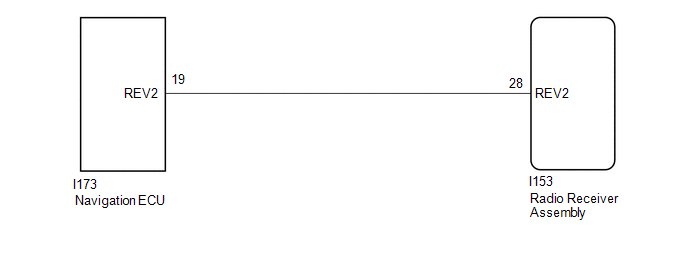
WIRING DIAGRAM
PROCEDURE
| 1. | CHECK HARNESS AND CONNECTOR (RADIO RECEIVER ASSEMBLY - NAVIGATION ECU) |
(a) Disconnect the I153 radio receiver assembly connector.
(b) Disconnect the I173 navigation ECU connector.
(c) Measure the resistance according to the value(s) in the table below.
Standard Resistance:
| Tester Connection | Condition | Specified Condition |
|---|---|---|
| I153-28 (REV2) - I173-19 (REV2) | Always | Below 1 Ω |
| I153-28 (REV2) - Body ground | Always | 10 kΩ or higher |
| OK | .gif) | PROCEED TO NEXT SUSPECTED AREA SHOWN IN PROBLEM SYMPTOMS TABLE |
.gif)
| NG | | REPAIR OR REPLACE HARNESS OR CONNECTOR |
READ NEXT:
 Start Up Signal Circuit between Radio Receiver Assembly and Navigation ECU
DESCRIPTION This circuit includes the navigation ECU and radio and display receiver assembly. WIRING DIAGRAM PROCEDURE 1. CHECK HARNESS AND CONNECTOR (RADIO RECEIVER ASSEMBLY - NAVIGATION ECU)
Microphone Circuit
DESCRIPTION
The radio receiver assembly and telephone microphone assembly are connected to each other using the microphone connection detection signal lines.
Using this circuit, the DCM (telemati
Visual Mute Signal Circuit between Radio Receiver and Multi-display
DESCRIPTION The radio receiver assembly sends a visual mute signal to the multi-display assembly. As a result, a black screen is inserted when the screen changes so that noise and distorted images are
SEE MORE:
Diagnosis System
DIAGNOSIS SYSTEM DESCRIPTION (a) When troubleshooting a vehicle with the diagnostic system, the only difference from the usual troubleshooting procedure is connecting the Techstream to the vehicle and reading various data output from the multiplex tilt and telescopic ECU. The multiplex tilt and tele
System Description
SYSTEM DESCRIPTION GENERAL (a) In the occupant classification system, the occupant detection ECU calculates the weight of the occupant based on signals from the occupant classification sensors. This system recognizes the occupant as a child if it detects a weight of less than 17 kg (37.4 lb) on the
© 2016-2026 Copyright www.lexunx.com
