Lexus NX: Back Camera Power Supply Failure (C1621)
DESCRIPTION
This DTC is stored if the rear television camera assembly judges as a result of its self check that the signals or signal lines between the rear television camera assembly and multi-display assembly are not normal.
| DTC No. | Detection Item | DTC Detection Condition | Trouble Area |
|---|---|---|---|
| C1621 | Back Camera Power Supply Failure | Rear television camera assembly power supply failure |
|
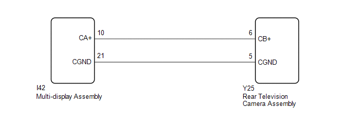
WIRING DIAGRAM
CAUTION / NOTICE / HINT
NOTICE:
-
When "!" mark is displayed on the multi-display assembly after disconnecting the cable from the negative (-) auxiliary batteryterminal, correct the steering angle neutral point.
Click here
.gif)
-
Depending on the parts that are replaced or operations that are performed during vehicle inspection or maintenance, calibration of other systems as well as the parking assist monitor system may be needed.
Click here
PROCEDURE
| 1. | CHECK HARNESS AND CONNECTOR (MULTI-DISPLAY ASSEMBLY - REAR TELEVISION CAMERA ASSEMBLY) |
(a) Disconnect the I42 multi-display assembly connector.
(b) Disconnect the Y25 rear television camera assembly connector.
(c) Measure the resistance according to the value(s) in the table below.
Standard Resistance:
| Tester Connection | Condition | Specified Condition |
|---|---|---|
| I42-10 (CA+) - Y25-6 (CB+) | Always | Below 1 Ω |
| I42-21 (CGND) - Y25-5 (CGND) | Always | Below 1 Ω |
| I42-10 (CA+) or Y25-6 (CB+) - Body ground | Always | 10 kΩ or higher |
| I42-21 (CGND) or Y25-5 (CGND) - Body ground | Always | 10 kΩ or higher |
| NG | .gif) | REPAIR OR REPLACE HARNESS OR CONNECTOR |
|
.gif)
| 2. | INSPECT MULTI-DISPLAY ASSEMBLY |
| (a) Disconnect the rear television camera assembly connector. |
|
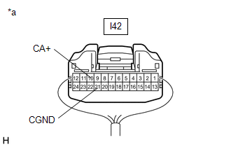
(b) Measure the resistance according to the value(s) in the table below.
Standard Resistance:
| Tester Connection | Condition | Specified Condition |
|---|---|---|
| I42-21 (CGND) - Body ground | Always | Below 1 Ω |
(c) Measure the voltage according to the value(s) in the table below.
Standard Voltage:
| Tester Connection | Condition | Specified Condition |
|---|---|---|
| I42-10 (CA+) - I42-21 (CGND) | Power switch on (ACC) | 5.5 to 7.05 V |
| I42-10 (CA+) - I42-21 (CGND) | Power switch off | Below 1 V |
| OK | | REPLACE REAR TELEVISION CAMERA ASSEMBLY |
| NG | | REPLACE MULTI-DISPLAY ASSEMBLY |
READ NEXT:
 Open or Short in Steering Angle Sensor +B (C1625)
DESCRIPTION This DTC is stored if the rear television camera assembly receives a signal via CAN communication from the steering sensor that indicates a power supply problem. DTC No. Detection Ite
Steering Angle Sensor Failure (C1626)
DESCRIPTION This DTC is stored if the rear television camera assembly receives a signal via CAN communication from the steering sensor that indicates an internal malfunction. DTC No. Detection It
Vehicle Information Unmatched (C168D)
DESCRIPTION This DTC is stored if the rear television camera assembly judges as a result of its self check that the vehicle information received from the main body ECU (multiplex network body ECU) via
SEE MORE:
CAN Communication Failure (Message Registry) (U1000)
DESCRIPTION If DTC U1000 is stored frequently, duplicate the problem symptoms and perform the inspection again even if the DTC is not output when rechecking for DTCs. DTC No. Detection Item DTC Detection Condition Trouble Area U1000 CAN Communication Failure (Message Registry) ECU m
Customize Parameters
CUSTOMIZE PARAMETERS CUSTOMIZE SLIDING ROOF SYSTEM HINT: The following items can be customized. NOTICE:
When the customer requests a change in a function, first make sure that the function can be customized.
Be sure to make notes of the current settings before customizing.
When troubleshootin
