Lexus NX: Calibration
CALIBRATION
TORQUE SENSOR ZERO POINT CALIBRATION (USING THE Techstream)
NOTICE:
Perform torque sensor zero point calibration if any of the following conditions occur:
- The power steering ECU assembly has been replaced.
- The electric power steering column sub-assembly has been replaced.
- There is a difference in steering effort between turning left and right.
(a) Perform inspection before calibration.
(1) Turn the power switch off.
(2) Connect the Techstream to the DLC3.
(3) Turn the power switch on (IG).
(4) Turn the Techstream on.
(5) Enter the following menus: Chassis / EMPS / Data List.
(6) Check the values by referring to the table below.
Chassis > EMPS > Data List| Tester Display | Measurement Item | Range | Normal Condition | Diagnostic Note |
|---|---|---|---|---|
| IG Power Supply | IG power source voltage | Min.: 0.0000 V Max.: 20.1531 V | Power switch on (IG): 8 to 16 V | - |
| Tester Display |
|---|
| IG Power Supply |
Standard voltage:
8 to 16 V
NOTICE:
If the IG power supply voltage is 8 V or less, calibration cannot be performed. In this case, charge or replace the auxiliary battery, and then perform calibration.
(b) Perform torque sensor zero point calibration.
(1) Set the steering wheel to the center point and align the front wheels straight ahead.
(2) Turn the power switch off.
(3) Connect the Techstream to the DLC3.
(4) Turn the power switch on (IG).
(5) Turn the Techstream on.
(6) Enter the following menus: Chassis / EMPS / Utility / Torque Sensor Adjustment.
Chassis > EMPS > Utility| Tester Display |
|---|
| Torque Sensor Adjustment |
NOTICE:
- Do not turn the steering wheel sharply.
- Do not touch the steering wheel during torque sensor zero point calibration.
(7) Check for DTCs.
Click here .gif)
NOTICE:
If DTC C1515, C1516 or C1534 is output, perform troubleshooting for the corresponding DTC.
ASSIST MAP WRITING (USING THE Techstream)
NOTICE:
Perform assist map writing if the following condition occurs:
The power steering ECU assembly has been replaced.
(a) Turn the power switch off.
(b) Connect the Techstream to the DLC3.
(c) Turn the power switch on (IG).
(d) Turn the Techstream on.
(e) Enter the following menus: Chassis / EMPS / Utility / Signal Check.
Chassis > EMPS > Utility| Tester Display |
|---|
| Signal Check |
HINT:
- Follow the instructions on the Techstream to perform Signal Check.
- With DTC C1581 output, performing Signal Check will cause the power steering ECU assembly to enter Test Mode and the assist map will be written automatically.
(f) Wait for 5 seconds or more.
(g) Check for DTCs.
Click here
HINT:
After writing the assist map, if DTC C1581 is output, perform the troubleshooting procedure for DTC C1581.
Click here
NOTICE:
Perform assist map writing if the following condition occurs:
The power steering ECU assembly has been replaced.
ASSIST MAP WRITING (USING SST CHECK WIRE)
(a) Turn the power switch off.
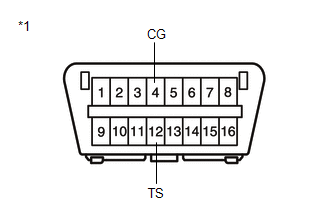
| *1 | DLC3 |
(b) Using SST, connect terminals 12 (TS) and 4 (CG) of the DLC3.
SST: 09843-18040
NOTICE:
Connect the terminals correctly to avoid a malfunction.
(c) Turn the power switch on (IG).
(d) Wait for 5 seconds or more.
(e) Check for DTCs.
Click here
HINT:
After writing the assist map, if DTC C1581 is output, perform the troubleshooting procedure for DTC C1581.
Click here
READ NEXT:
 Problem Symptoms Table
PROBLEM SYMPTOMS TABLE HINT:
Use the table below to help determine the cause of problem symptoms. If multiple suspected areas are listed, the potential causes of the symptoms are listed in order of
Terminals Of Ecu
TERMINALS OF ECU *a Component with harness connected (Power Steering ECU Assembly) - - CHECK POWER STEERING ECU ASSEMBLY (a) Measure the voltage and resistance according to the value(s) i
Diagnosis System
DIAGNOSIS SYSTEM CHECK DLC3 (a) Check the DLC3. Click here CHECK WARNING LIGHT (a) When a problem occurs in the power steering system, the power steering warning light (red or yellow) on the combina
SEE MORE:
System Description
SYSTEM DESCRIPTION SYSTEM DESCRIPTION (a) The electric parking brake system electronically controls the parking brake lock and release operations using actuators. The main functions are as follows: Functions when vehicle stopped
When the electric parking brake switch (integration control and pane
Precaution
PRECAUTION PRECAUTION FOR DISCONNECTING CABLE FROM NEGATIVE AUXILIARY BATTERY TERMINAL NOTICE:
After the power switch is turned off, there may be a waiting time before disconnecting the negative (-) auxiliary battery terminal.
Click here
When disconnecting and reconnecting the auxiliary batte
