Lexus NX: Terminals Of Ecu
TERMINALS OF ECU
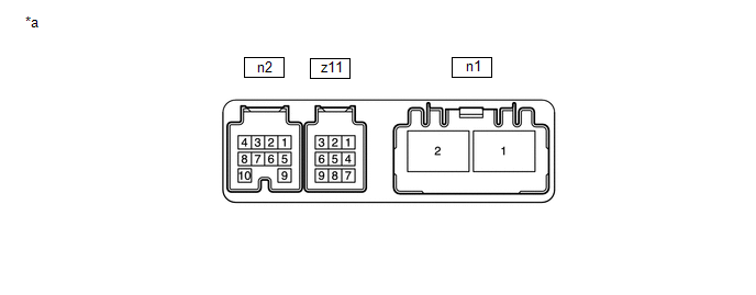
| *a | Component with harness connected (Power Steering ECU Assembly) | - | - |
CHECK POWER STEERING ECU ASSEMBLY
(a) Measure the voltage and resistance according to the value(s) in the table below.
NOTICE:
When the power steering warning light (red) is illuminated due to a malfunction, the fail-safe function may cause the voltage of the power steering ECU assembly terminals to become 0 V.
| Terminal No. (Symbol) | Wiring Color | Terminal Description | Condition | Specified Condition |
|---|---|---|---|---|
| n2-1 (IG) - Body ground | R - Body ground | IG power source | Power switch on (IG) | 8 to 16 V |
| n2-6 (TS) - Body ground | G - Body ground | Test mode signal | Always | 9 to 16 V |
| n2-7 (CANH) - n2-8 (CANL) | W - B | CAN communication line | Power switch off | 54 to 69 Ω |
| z11-8 (TRQV) - z11-2 (TRQG) | R - B | Torque sensor voltage source | Power switch on (IG) | 4.5 to 5.5 V |
| z11-1 (TRQ2) - z11-2 (TRQG) | Y - B | Torque sensor 2 signal | Power switch on (READY), steering wheel not being turned (without load) | 2.3 to 2.7 V |
| Power switch on (READY), steering wheel being turned to the right with vehicle stopped | 1.2 to 2.5 V | |||
| Power switch on (READY), steering wheel being turned to the left with vehicle stopped | 2.5 to 3.8 V | |||
| z11-2 (TRQG) - Body ground | B - Body ground | Torque sensor ground | Always | Below 1 Ω |
| z11-9 (TRQ1) - z11-2 (TRQG) | W - B | Torque sensor 1 signal | Power switch on (READY), steering wheel not being turned (without load) | 2.3 to 2.7 V |
| Power switch on (READY), steering wheel being turned to the left with vehicle stopped | 1.2 to 2.5 V | |||
| Power switch on (READY), steering wheel being turned to the right with vehicle stopped | 2.5 to 3.8 V | |||
| n1-1 (PIG) - Body ground | R - Body ground | Power source | Always | 9 to 16 V |
| n1-2 (PGND) - Body ground | B - Body ground | Power ground | Always | Below 1 Ω |
READ NEXT:
 Diagnosis System
DIAGNOSIS SYSTEM CHECK DLC3 (a) Check the DLC3. Click here CHECK WARNING LIGHT (a) When a problem occurs in the power steering system, the power steering warning light (red or yellow) on the combina
Dtc Check / Clear
DTC CHECK / CLEAR CHECK DTC (USING THE Techstream) (a) Turn the power switch off. (b) Connect the Techstream to the DLC3. (c) Turn the power switch on (IG). (d) Turn the Techstream on. (e) Enter the f
Freeze Frame Data
FREEZE FRAME DATA FREEZE FRAME DATA NOTICE:
It is difficult to show the specified values (judgment values) clearly because freeze frame data values change significantly due to differences in measur
SEE MORE:
Back Door Closer Operation Malfunction (B2250)
DESCRIPTION The multiplex network door ECU receives signals from the latch switch, initial switch, pawl switch and back door courtesy switch, which are built into the back door lock assembly. Based on these switch signals, the latch position of the back door lock assembly is determined. DTC No.
Turn Signal Switch Circuit
DESCRIPTION The combination meter receives the turn signal switch information and controls the turn signal lights. WIRING DIAGRAM CAUTION / NOTICE / HINT NOTICE: When replacing the combination meter assembly, make sure to replace it with a new one. PROCEDURE 1. READ VALUE USING TECHSTREAM (TU
