Lexus NX: Components
COMPONENTS
ILLUSTRATION
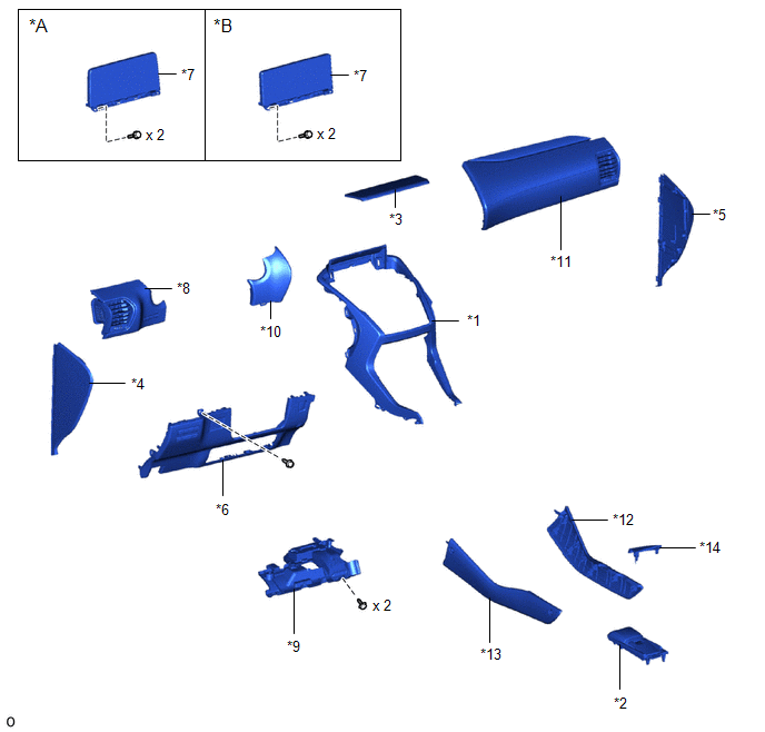
| *A | for 8 Inch Display | *B | for 10.3 Inch Display |
| *1 | CENTER INSTRUMENT CLUSTER FINISH PANEL ASSEMBLY | *2 | CONSOLE ARMREST ASSEMBLY |
| *3 | INSTRUMENT PANEL FINISH PLATE | *4 | INSTRUMENT SIDE PANEL LH |
| *5 | INSTRUMENT SIDE PANEL RH | *6 | LOWER NO. 1 INSTRUMENT PANEL FINISH PANEL |
| *7 | MULTI-DISPLAY ASSEMBLY WITH BRACKET | *8 | NO. 1 INSTRUMENT PANEL SAFETY PAD SUB-ASSEMBLY |
| *9 | NO. 1 INSTRUMENT PANEL UNDER COVER SUB-ASSEMBLY | *10 | NO. 1 SWITCH HOLE BASE |
| *11 | NO. 2 INSTRUMENT PANEL SAFETY PAD SUB-ASSEMBLY | *12 | UPPER NO. 1 CONSOLE PANEL GARNISH |
| *13 | UPPER NO. 2 CONSOLE PANEL GARNISH | *14 | UPPER REAR CONSOLE PANEL |
ILLUSTRATION
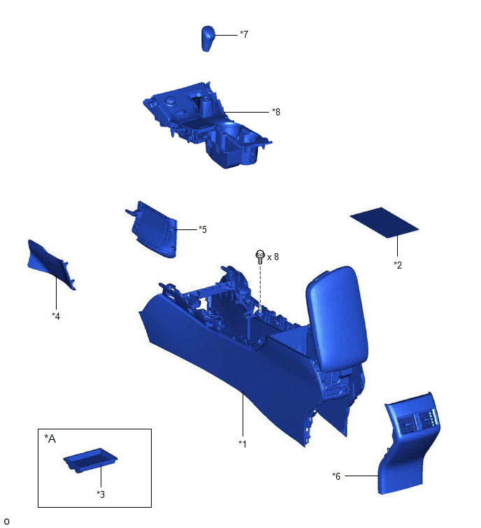
| *A | w/o Wireless Charger | - | - |
| *1 | CONSOLE BOX ASSEMBLY | *2 | CONSOLE BOX CARPET |
| *3 | CONSOLE BOX POCKET | *4 | INNER NO. 1 INSTRUMENT PANEL BRACE COVER LH |
| *5 | INNER NO. 1 INSTRUMENT PANEL BRACE COVER RH | *6 | REAR CONSOLE END PANEL SUB-ASSEMBLY |
| *7 | SHIFT LEVER KNOB SUB-ASSEMBLY | *8 | UPPER REAR CONSOLE PANEL SUB-ASSEMBLY |
ILLUSTRATION
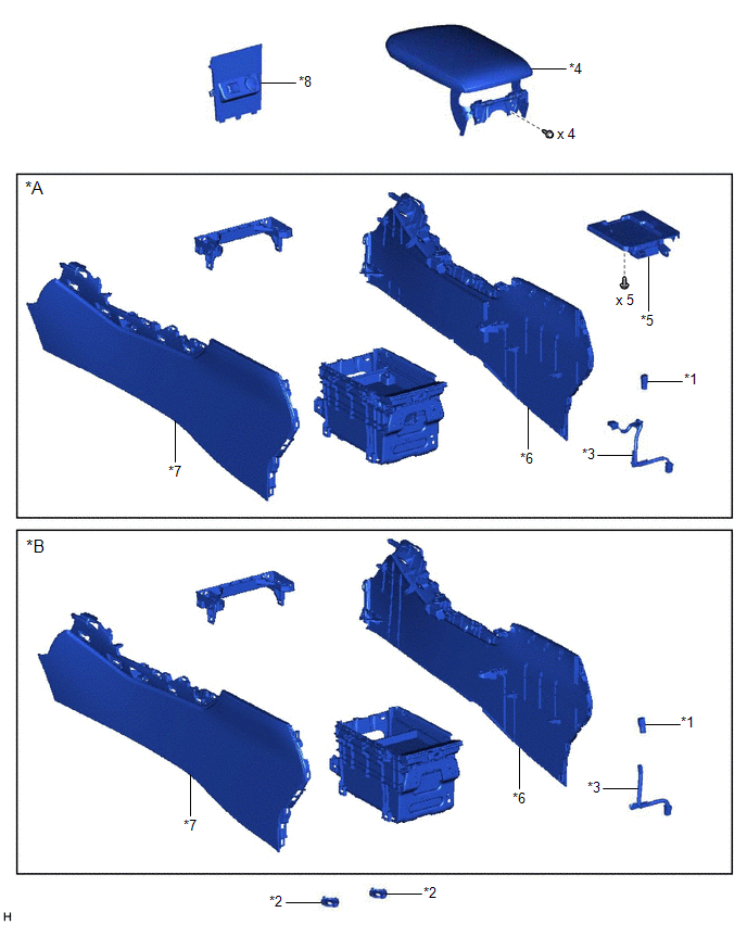
| *A | w/ Wireless Charger | *B | w/o Wireless Charger |
| *1 | CONSOLE BOX ILLUMINATION LIGHT ASSEMBLY | *2 | CONSOLE BOX PLATE |
| *3 | CONSOLE BOX WIRE | *4 | CONSOLE COMPARTMENT DOOR SUB-ASSEMBLY |
| *5 | MOBILE WIRELESS CHARGER CRADLE ASSEMBLY | *6 | NO. 1 BOX SIDE PANEL |
| *7 | NO. 2 BOX SIDE PANEL | *8 | NO. 3 BOX PANEL |
ILLUSTRATION
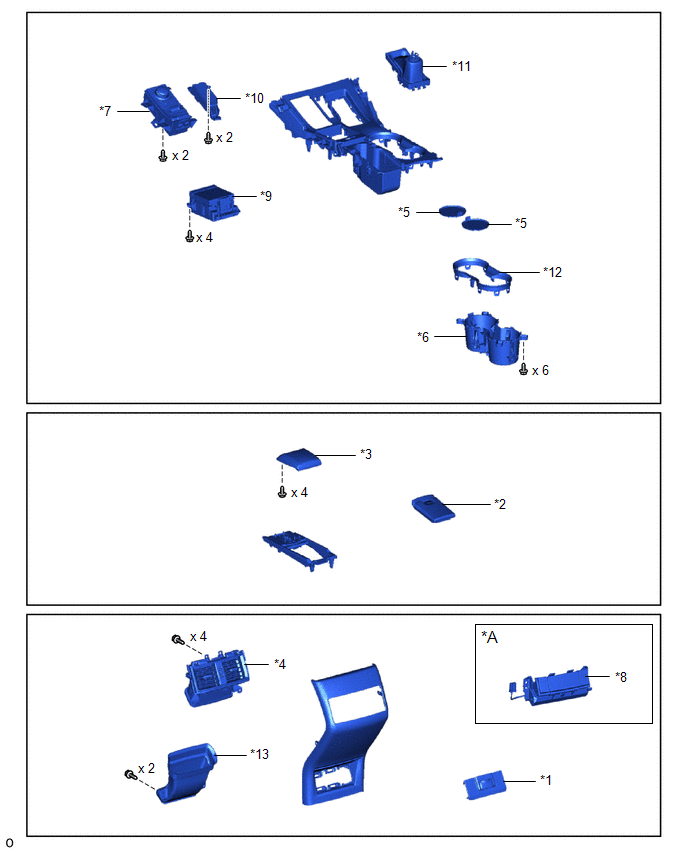
| *A | w/ Rear Seat Heater | - | - |
| *1 | CIGARETTE LIGHTER COVER | *2 | CONSOLE ARMREST LID |
| *3 | CONSOLE BOX POCKET SUB-ASSEMBLY | *4 | CONSOLE BOX REGISTER ASSEMBLY |
| *5 | CONSOLE COMPARTMENT BOX | *6 | CONSOLE CUP HOLDER BOX SUB-ASSEMBLY |
| *7 | INTEGRATION CONTROL AND PANEL ASSEMBLY | *8 | REFRESHING SEAT SWITCH |
| *9 | REMOTE OPERATION CONTROLLER ASSEMBLY | *10 | SHIFT POSITION INDICATOR |
| *11 | SHIFTING HOLE COVER SUB-ASSEMBLY | *12 | CUP HOLDER RAIL |
| *13 | DUCT | - | - |
READ NEXT:
 Removal
REMOVAL PROCEDURE 1. REMOVE CONSOLE ARMREST ASSEMBLY Click here 2. REMOVE UPPER REAR CONSOLE PANEL Click here 3. REMOVE UPPER NO. 2 CONSOLE PANEL GARNISH Click here 4. REMOVE UPPER NO. 1 CONS
Disassembly
DISASSEMBLY PROCEDURE 1. REMOVE CONSOLE COMPARTMENT DOOR SUB-ASSEMBLY (a) Remove the 4 screws and console compartment door sub-assembly. 2. REMOVE NO. 3 BOX PANEL (a) Detach the 2 cl
Installation
INSTALLATION CAUTION / NOTICE / HINT HINT: A bolt without a torque specification is shown in the standard bolt chart. Click here PROCEDURE 1. INSTALL CONSOLE BOX ASSEMBLY (a) Attach the 4 guides to
SEE MORE:
Front passenger occupant classification
system
Your vehicle is equipped with a front passenger occupant classification
system.
This system detects the conditions of the front passenger seat and activates
or deactivates the front passenger airbag and seat cushion airbag in the
front passenger side.
System components
SRS warning ligh
Components
COMPONENTS ILLUSTRATION *A w/ Woofer *B w/o Woofer *C w/o Power Back Door *D w/ Power Back Door *1 BACK DOOR CENTER GARNISH *2 BACK DOOR FINISH COVER LH *3 BACK DOOR FINISH COVER RH *4 BACK DOOR LOCK COVER *5 BACK DOOR SIDE GARNISH LH *6 BACK DOOR SI
