Lexus NX: Components
COMPONENTS
ILLUSTRATION
.png)
| *1 | DECK FLOOR BOX LH | *2 | NO. 3 DECK BOARD SUB-ASSEMBLY |
| *3 | REAR DECK FLOOR BOX | *4 | AUXILIARY BATTERY NEGATIVE TERMINAL |
.png) | N*m (kgf*cm, ft.*lbf): Specified torque | - | - |
ILLUSTRATION
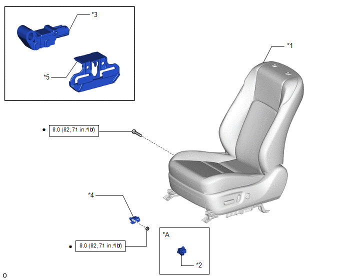
| *A | w/ Seat Heater System | - | - |
| *1 | FRONT SEAT ASSEMBLY LH | *2 | SEAT HEATER CONTROL SUB-ASSEMBLY LH |
| *3 | SEAT POSITION AIRBAG SENSOR | *4 | SEAT POSITION AIRBAG SENSOR WITH SEAT SLIDE POSITION SENSOR PROTECTOR |
| *5 | SEAT SLIDE POSITION SENSOR PROTECTOR | - | - |
| | N*m (kgf*cm, ft.*lbf): Specified torque | ● | Non-reusable part |
READ NEXT:
 On-vehicle Inspection
ON-VEHICLE INSPECTION CAUTION / NOTICE / HINT CAUTION: Be sure to follow the correct removal and installation procedures of the seat position airbag sensor. PROCEDURE 1. INSPECT SEAT POSITION AIRBAG S
Removal
REMOVAL CAUTION / NOTICE / HINT CAUTION: Wear protective gloves. Sharp areas on the parts may injure your hands. PROCEDURE 1. REMOVE NO. 3 DECK BOARD SUB-ASSEMBLY Click here 2. REMOVE REAR DECK FLOO
Installation
INSTALLATION CAUTION / NOTICE / HINT CAUTION: Wear protective gloves. Sharp areas on the parts may injure your hands. PROCEDURE 1. INSTALL SEAT POSITION AIRBAG SENSOR (a) Align the adjustment suppo
SEE MORE:
How To Proceed With Troubleshooting
PROCEDURE 1. CHECK TIRE AND WHEEL SYSTEM DIAGNOSIS OF IRREGULAR TIRE WEAR GO TO STEP 11
DIAGNOSIS OF TIRE VIBRATION 2. TIGHTEN WHEEL NUTS
NEXT 3. INSPECT TIRES Click here NG GO TO STEP 10
OK 4.
Data List / Active Test
DATA LIST / ACTIVE TEST DATA LIST HINT: Using the Techstream to read the Data List allows the values or states of switches, sensors, actuators and other items to be read without removing any parts. This non-intrusive inspection can be very useful because intermittent conditions or signals may be dis
© 2016-2026 Copyright www.lexunx.com
