Lexus NX: Components
Lexus NX Service Manual / Brake / Brake Control / Dynamic Control Systems / Vsc Off Switch / Components
COMPONENTS
ILLUSTRATION
.png)
| *1 | CENTER INSTRUMENT CLUSTER FINISH PANEL ASSEMBLY | *2 | INSTRUMENT SIDE PANEL LH |
| *3 | INSTRUMENT SIDE PANEL RH | *4 | LOWER NO. 1 INSTRUMENT PANEL FINISH PANEL |
| *5 | NO. 1 INSTRUMENT PANEL SAFETY PAD SUB-ASSEMBLY | *6 | NO. 1 INSTRUMENT PANEL UNDER COVER SUB-ASSEMBLY |
| *7 | NO. 1 SWITCH HOLE BASE | *8 | NO. 2 INSTRUMENT PANEL SAFETY PAD SUB-ASSEMBLY |
| *9 | UPPER NO. 1 CONSOLE PANEL GARNISH | *10 | UPPER NO. 2 CONSOLE PANEL GARNISH |
ILLUSTRATION
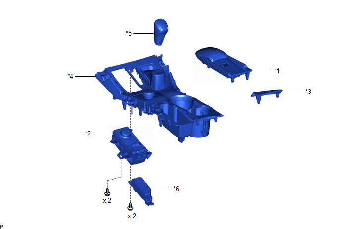
| *1 | CONSOLE ARMREST ASSEMBLY | *2 | INTEGRATION CONTROL AND PANEL ASSEMBLY (VSC OFF SWITCH) |
| *3 | REAR UPPER CONSOLE PANEL | *4 | REAR UPPER CONSOLE PANEL SUB-ASSEMBLY |
| *5 | SHIFT LEVER KNOB SUB-ASSEMBLY | *6 | SHIFT POSITION INDICATOR |
READ NEXT:
 Removal
REMOVAL PROCEDURE 1. REMOVE CONSOLE ARMREST ASSEMBLY Click here 2. REMOVE REAR UPPER CONSOLE PANEL Click here 3. REMOVE UPPER NO. 2 CONSOLE PANEL GARNISH Click here 4. REMOVE UPPER NO. 1 C
Inspection
INSPECTION PROCEDURE 1. INSPECT INTEGRATION CONTROL AND PANEL ASSEMBLY (VSC OFF SWITCH) (a) Measure the resistance according to the value(s) in the table below. Standard Resistance: Tester Conn
Installation
INSTALLATION PROCEDURE 1. INSTALL INTEGRATION CONTROL AND PANEL ASSEMBLY (VSC OFF SWITCH) (a) Install the integration control and panel assembly (VSC OFF switch) to the upper rear console panel sub
SEE MORE:
Reassembly
REASSEMBLY PROCEDURE 1. INSTALL ROOF WIND DEFLECTOR PANEL SUB-ASSEMBLY (a) Attach the 2 guides as shown in the illustration to install the roof wind deflector panel sub-assembly. (b) Attach the 2 springs as shown in the illustration. *a Spring - - NOTICE: Make sure that the springs are
Disposal
DISPOSAL PROCEDURE 1. DISPOSE OF BRAKE BOOSTER PUMP ASSEMBLY (a) Remove the accumulator from the brake booster pump assembly. (b) Secure the accumulator in a vise. (c) Using a hacksaw, make a cut in the side of the accumulator within location (A) to release the high-pressure gas. Location Le
© 2016-2026 Copyright www.lexunx.com
