Lexus NX: DCM Data Signal Circuit between Navigation ECU and DCM
DESCRIPTION
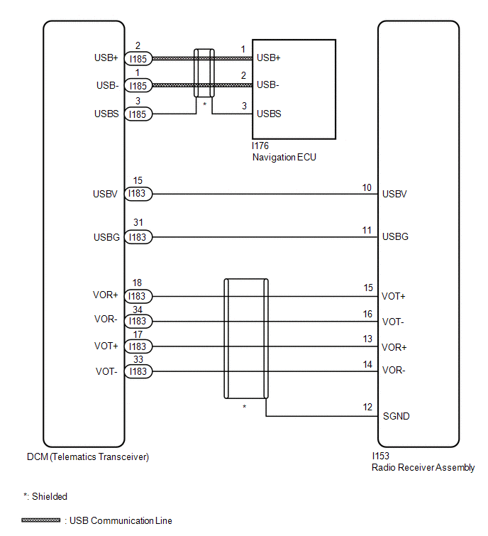
This circuit is used to send and receive signals between the DCM (telematics transceiver) and radio receiver assembly.
WIRING DIAGRAM
PROCEDURE
| 1. | CHECK HARNESS AND CONNECTOR (DCM [TELEMATICS TRANSCEIVER] - RADIO RECEIVER ASSEMBLY) |
(a) Disconnect the I153 radio receiver assembly connector.
(b) Disconnect the I183 DCM (telematics transceiver) connector.
(c) Measure the resistance according to the value(s) in the table below.
Standard Resistance:
| Tester Connection | Condition | Specified Condition |
|---|---|---|
| I153-10 (USBV) - I183-15 (USBV) | Always | Below 1 Ω |
| I153-11 (USBG) - I183-31 (USBG) | Always | Below 1 Ω |
| I153-15 (VOT+) - I183-18 (VOR+) | Always | Below 1 Ω |
| I153-16 (VOT-) - I183-34 (VOR-) | Always | Below 1 Ω |
| I153-13 (VOR+) - I183-17 (VOT+) | Always | Below 1 Ω |
| I153-14 (VOR-) - I183-33 (VOT-) | Always | Below 1 Ω |
| I153-10 (USBV) - Body ground | Always | 10 kΩ or higher |
| I153-11 (USBG) - Body ground | Always | 10 kΩ or higher |
| I153-15 (VOT+) - Body ground | Always | 10 kΩ or higher |
| I153-16 (VOT-) - Body ground | Always | 10 kΩ or higher |
| I153-13 (VOR+) - Body ground | Always | 10 kΩ or higher |
| I153-14 (VOR-) - Body ground | Always | 10 kΩ or higher |
| I153-12 (SGND) - Body ground | Always | 10 kΩ or higher |
| NG | .gif) | REPAIR OR REPLACE HARNESS OR CONNECTOR |
|
.gif)
| 2. | CHECK HARNESS AND CONNECTOR (DCM [TELEMATICS TRANSCEIVER] - NAVIGATION ECU) |
| (a) Disconnect the I176 navigation ECU connector. |
|
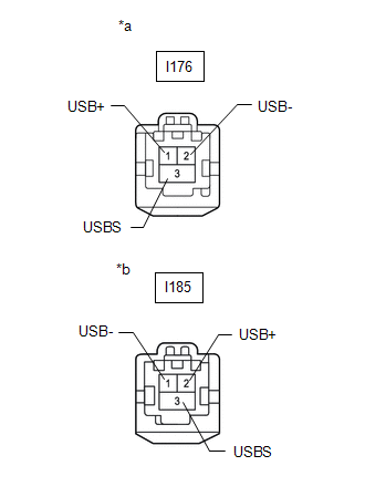
(b) Disconnect the I185 DCM (telematics transceiver) connector.
(c) Measure the resistance according to the value(s) in the table below.
Standard Resistance:
| Tester Connection | Condition | Specified Condition |
|---|---|---|
| I176-1 (USB+) - I185-2 (USB+) | Always | Below 1 Ω |
| I176-2 (USB-) - I185-1 (USB-) | Always | Below 1 Ω |
| I176-3 (USBS) - I185-3 (USBS) | Always | Below 1 Ω |
| I176-1 (USB+) - Body ground | Always | 10 kΩ or higher |
| I176-2 (USB-) - Body ground | Always | 10 kΩ or higher |
| I176-3 (USBS) - Body ground | Always | 10 kΩ or higher |
| OK | | PROCEED TO NEXT SUSPECTED AREA SHOWN IN PROBLEM SYMPTOMS TABLE |
| NG | | REPAIR OR REPLACE HARNESS OR CONNECTOR |
READ NEXT:
 Manual(sos)switch
InspectionINSPECTION PROCEDURE 1. REMOVE MAP LIGHT ASSEMBLY Click here 2. INSPECT MAP LIGHT ASSEMBLY (a) Check the resistance. (1) Measure the resistance according to the value(s) in the table belo
Components
COMPONENTS ILLUSTRATION *1 DECK FLOOR BOX LH *2 NO. 3 DECK BOARD SUB-ASSEMBLY *3 REAR DECK FLOOR BOX *4 NEGATIVE AUXILIARY BATTERY TERMINAL N*m (kgf*cm, ft.*lbf): Specified
SEE MORE:
Oxygen Sensor Circuit (Bank 1 Sensor 2) (P0136-P0139,P013A)
DESCRIPTION In order to obtain a high purification rate of the carbon monoxide (CO), hydrocarbon (HC) and nitrogen oxide (NOx) components in the exhaust gas, a TWC (Three-Way Catalytic Converter) is used. For the most efficient use of the TWC, the air fuel ratio must be precisely controlled so that
Precaution
PRECAUTION HANDLING PRECAUTION FOR ROAD SIGN ASSIST SYSTEM (a) The system may not detect traffic signs under the following conditions:
The forward recognition camera is misaligned.
Dirt, snow, ice or a sticker is on the windshield glass in front of the forward recognition camera.
The windshie
