- Device Name List No. 1 displays some of the devices that make up the audio and visual system.
- The names of the components from Device Name List No. 1 are shown in the following table.
Lexus NX: Dtc Check / Clear
Lexus NX Service Manual / Audio & Visual & Telematics / Audio / Video / Audio And Visual System / Dtc Check / Clear
DTC CHECK / CLEAR
CHECK DTC (CHECK USING Techstream)
(a) Connect the Techstream to the DLC3.
(b) Turn the power switch on (IG) and wait for 90 seconds.
(c) Turn the Techstream on.
(d) Enter the following menus: Body Electrical / Navigation System / Trouble Codes.
Body Electrical > Navigation System > Trouble Codes(e) Check for DTCs, and then write them down.
(f) Check the details of the DTC(s).
Click here .gif)
CLEAR DTC (CLEAR USING Techstream)
(a) Connect the Techstream to the DLC3.
(b) Turn the power switch on (IG) and wait for 90 seconds.
(c) Turn the Techstream on.
(d) Enter the following menus: Body Electrical / Navigation System / Trouble Codes.
Body Electrical > Navigation System > Clear DTCs(e) Clear the DTCs.
START DIAGNOSTIC MODE
HINT:
- Illustrations may differ from the actual vehicle screen depending on the device settings and options. Therefore, some detailed areas may not be shown exactly the same as on the actual vehicle screen.
- After the power switch is turned on (IG), check that the home is displayed before starting diagnostic mode. Otherwise, some items cannot be checked.
- Start diagnostic mode using either of the 3 methods below.
(a) Method 1:
(1) Turn the power switch on (IG).
(2) While pressing and holding the "MENU" switch, operate the light control switch: Off → Tail → Off → Tail → Off → Tail → Off.
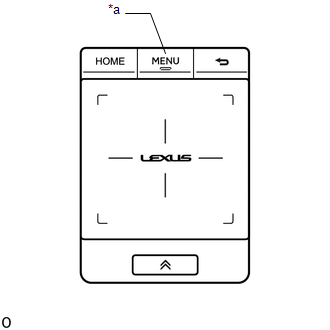
| *a | "MENU" Switch |
(3) Diagnostic mode starts and the "Service Menu" screen will be displayed. Service inspection starts automatically and the result will be displayed.
(b) Method 2:
NOTICE:
- If the operation fails and diagnostic mode cannot be entered, turn the multi-display assembly screen display on and off once, and then perform the procedures listed below from the first step again. (Only turning the radio receiver assembly power supply on and off will not work.)
- Do not touch the touch screen except when required.
- Since the remote touch screen may recognize a pinch in/out or flick operation if operated with 2 fingers, always use 1 finger to operate the remote touch in diagnostic mode.
(1) Turn the power switch on (IG).
(2) Turn the multi-display assembly screen display off.
(3) Turn the radio receiver assembly power supply off.
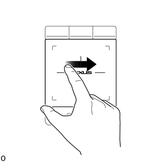
(4) Perform the "left to right flick" operation on the touch pad 5 times as shown in the illustration.
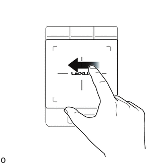
(5) Perform the "right to left flick" operation on the touch pad 5 times as shown in the illustration.
HINT:
- Complete the operation within 15 seconds of the first "left to right flick" operation.
- Perform a flick operation at the center of the remote touch screen.
(6) Diagnostic mode starts and the "Service Menu" screen will be displayed. Service inspection starts automatically and the result will be displayed.
(c) Method 3:
(1) Connect the Techstream to the DLC3.
(2) Turn the power switch on (IG).
(3) Turn the Techstream on.
(4) Enter the following menus: Body Electrical / Navigation System / Utility / Map Information.
Body Electrical > Navigation System > Utility| Tester Display |
|---|
| Diagnostic Mode |
(5) Diagnostic mode starts and the "Service Menu" screen will be displayed. Service inspection starts automatically and the result will be displayed.
(d) Method 4:
NOTICE:
If the operation fails and diagnostic mode cannot be entered, turn the multi-display assembly screen display on and off once, and then perform the procedures listed below from the first step again. (Only turning the radio receiver assembly power supply on and off will not work.)
(1) Turn the power switch on (IG).
(2) Turn the multi-display assembly screen display off.
(3) Turn the radio receiver assembly power supply off.
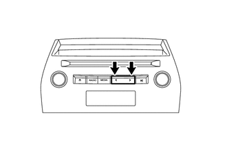
(4) Press the ">" switch 5 times, and then press the "<" switch 5 times within 15 seconds.
(5) Diagnostic mode starts and the "Service Menu" screen will be displayed. Service inspection starts automatically and the result will be displayed.
FAILURE DIAGNOSIS
(a) The "Failure Diagnosis" screen will be displayed by pressing the "Failure Diagnosis" switch on the "Service Menu" screen.
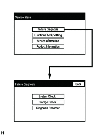
SYSTEM CHECK
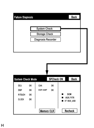
(a) The "System Check Mode" screen will be displayed by selecting "System Check" on the "Failure Diagnosis" screen.
CHECK DTC (CHECK USING SYSTEM CHECK MODE SCREEN)
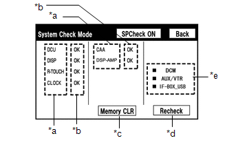
(a) System check mode screen description
 Screen Description
 | Display | Content |
|---|---|
| *a: Device Name List No. 1 | |
| *b: Check Result | Result codes for all devices are displayed. |
| *c: Memory Clear |
|
| *d: Recheck |
|
| *e: Device Name List No. 2 |
|
| Name | Component | Connection Method |
|---|---|---|
| DCU | Radio Receiver Assembly | - |
| DISP | Multi-display assembly | Communication line for AVC-LAN |
| R-TOUCH | Remote operation controller assembly (remote touch) | Local bus communication line |
| CLOCK | Clock assembly | Local bus communication line |
| CAA | Television camera assembly | Vehicle wire harness |
| DSP-AMP | Stereo component amplifier assembly | Communication line for AVC-LAN |
| Result | Meaning | Action |
|---|---|---|
| OK | The device does not respond with a DTC. | - |
| NCON | The device was previously present, but does not respond in diagnostic mode. | - Check power supply wire harness of the device. - Check the AVC-LAN communication line of the device. |
| NRES | The device responds in diagnostic mode, but gives no DTC information. | - Check power supply wire harness of the device. - Check the AVC-LAN communication line of the device. |
| Name | Component | Connection Method |
|---|---|---|
| *: w/ Manual (SOS) Switch | ||
| DCM* | DCM (telematics transceiver) | Communication line for USB |
| AUX/VTR | No. 1 stereo jack adapter assembly | Vehicle wire harness |
| IF-BOX_ USB | No. 1 stereo jack adapter assembly | Communication line for USB |
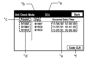
(b) Unit check mode screen description
 Screen Description
 | Display | Content |
|---|---|
| *a: Device name | Target device |
| *b: History DTC | Diagnostic memory results and stored DTCs are displayed. |
| *c: Present DTC | DTCs output in the service check are displayed. |
| *d: DTC | DTC (Diagnostic Trouble Code) |
| *e: Timestamp | The time and date of history DTCs are displayed. (The year is displayed in 2-digit format.) |
| *f: Diagnosis clear switch | Selecting "Code CLR" for 3 seconds clears the diagnostic memory data of the target device. (Both diagnostic system check result and the displayed data are cleared.) |
HINT:
- This screen is updated once per second.
- A maximum of 6 DTCs can be displayed for history and present DTCs.
(c) Read the system check result.
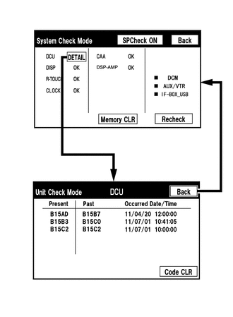
(1) If the check result is "DETAIL", select the displayed check result to view the results on the "Unit Check Mode" screen and record them.
NOTICE:
A maximum of 6 DTCs can be displayed for history and present DTCs on the "Unit Check Mode" screen. Therefore, when 6 DTCs are displayed, troubleshoot those DTCs first and then check the "Unit Check Mode" screen again to see if any other DTCs are displayed.
HINT:
- When all results are "OK", no DTCs are stored.
-
When "NCON" is displayed for all devices connected via the AVC-LAN, or when all device names are not displayed, check if there is a short circuit in the AVC-LAN or devices connected to the AVC-LAN. Repair or replace parts as necessary.
Click here
- When proceeding to view the results of another device, select the "Back" switch to return to the "System Check Mode" screen. Repeat the above step to view the results of other devices.
(2) Check the details of the DTC(s).
Click here
NOTICE:
The audio and visual system outputs DTCs for the following system. When DTCs other than those in Diagnostic Trouble Code Chart for the audio and visual system are output, refer to Diagnostic Trouble Code Chart for the relevant system.
| System | Proceed to |
|---|---|
| *: w/ Manual (SOS) Switch | |
| Parking Assist Monitor System | |
| Safety Connect System* | |
| Lexus Enform System* | |
DTC CLEAR/RECHECK (CLEAR USING SYSTEM CHECK MODE SCREEN)
(a) Clear DTCs
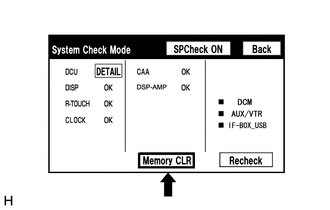
(1) Select "Memory CLR" for 3 seconds.
(2) Confirm that the check results are cleared.
HINT:
- To clear the DTCs for a specific device, clear the DTCs using the "Unit Check Mode" screen.
- When clearing DTCs using the "Unit Check Mode" screen, select "Code CLR" for 3 seconds.
(b) Recheck
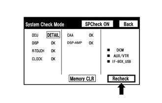
(1) Press the "Recheck" switch.
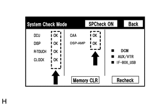
(2) Confirm that all diagnostic codes are "OK" when the check results are displayed. If a result other than "OK" is displayed, perform troubleshooting again.
HINT:
When the DTCs are cleared using the "Unit Check Mode" screen, select "Back" to return to the "System Check Mode" screen and perform this operation.
FINISH DIAGNOSTIC MODE
(a) Turn the power switch off.
READ NEXT:
 Freeze Frame Data
FREEZE FRAME DATA CHECK FREEZE FRAME DATA (a) Connect the Techstream to the DLC3. (b) Turn the power switch on (IG). (c) Turn the Techstream on. (d) Enter the following menus: Body Electrical / Naviga
Data List / Active Test
DATA LIST / ACTIVE TEST DATA LIST NOTICE: In the table below, the values listed under "Normal Condition" are reference values. Do not depend solely on these reference values when deciding whether a pa
Diagnostic Trouble Code Chart
DIAGNOSTIC TROUBLE CODE CHART Audio and Visual System DTC No. Detection Item Link B1323 Lost Communication with Haptic Device B1324 Lost Communication with Meter B1325
SEE MORE:
Parts Location
PARTS LOCATION ILLUSTRATION *A w/ Memory *B w/ Pre-collision System *C for Triple Beam Headlight - - *1 FORWARD RECOGNITION CAMERA *2 OUTER MIRROR CONTROL ECU ASSEMBLY RH *3 OUTER MIRROR CONTROL ECU ASSEMBLY LH *4 ECM *5 BRAKE BOOSTER WITH MASTER CYLINDE
Head restraints
Head restraints are provided for all
seats.
WARNING
■Head restraint precautions
Observe the following precautions
regarding the head restraints.
Failure to do so may result in death or
serious injury.
Use the head restraints designed for
each respective seat.
Adjust the head restr
© 2016-2026 Copyright www.lexunx.com
