Lexus NX: Removal
REMOVAL
CAUTION / NOTICE / HINT
NOTICE:
- The type of battery voltage sensor to be used varies depending on the vehicle model.
- If the wrong type of battery voltage sensor is installed, the power switch cannot be turned on (READY).
-
After installing the battery voltage sensor, perform the following to check that the power switch can be turned on (READY).
- Turn the power switch on (READY).
- Turn the power switch off and wait for 30 seconds or more.
- Turn the power switch on (READY) again.
PROCEDURE
1. PRECAUTION
Click here .gif)
2. CHECK FOR DTC
(a) Check for DTC.
Click here
NOTICE:
Confirm that P0AA6 (Hybrid Battery Voltage System Isolation Fault) is not output before removing or installing the HV battery. If this DTC is output, perform troubleshooting for this DTC first.
Click here
3. REMOVE HV BATTERY JUNCTION BLOCK ASSEMBLY
Click here
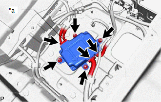
4. REMOVE LOWER NO. 2 HYBRID BATTERY CARRIER PATCH
CAUTION:
Wear insulated gloves and use insulated tools.
| (a) Disconnect the wire harness clamp. |
|
(b) Remove the 3 nuts, bolt and lower No. 2 hybrid battery carrier patch.
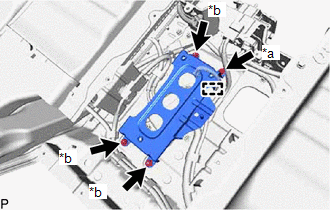
5. REMOVE BATTERY VOLTAGE SENSOR
CAUTION:
Wear insulated gloves and use insulated tools.
| (a) Disconnect the 3 battery voltage sensor connectors. NOTICE:
|
|
(b) Remove the 4 nuts and battery voltage sensor.
READ NEXT:
 Installation
INSTALLATION CAUTION / NOTICE / HINT NOTICE:
The type of battery voltage sensor to be used varies depending on the vehicle model.
If the wrong type of battery voltage sensor is installed, the pow
On-vehicle Inspection
ON-VEHICLE INSPECTION PROCEDURE 1. INSPECT FOR COOLANT LEAK (for Inverter Coolant) (a) Remove the inverter reserve tank cap. CAUTION: To avoid the danger of being burned, do not remove the inverter re
SEE MORE:
Removal
REMOVAL PROCEDURE 1. REMOVE CONSOLE ARMREST ASSEMBLY Click here 2. REMOVE UPPER REAR CONSOLE PANEL Click here 3. REMOVE UPPER NO. 2 CONSOLE PANEL GARNISH Click here 4. REMOVE UPPER NO. 1 CONSOLE PANEL GARNISH Click here 5. REMOVE INSTRUMENT SIDE PANEL LH Click here 6. REMOVE NO. 1 INSTRUME
Master Module Horizontal Axis Misalignment (C1AC1)
DESCRIPTION This DTC is stored when the angle of the blind spot monitor sensor LH deviates more than the allowable range from the horizontal axis. HINT: If a drum tester such as a speedometer tester, brake/speedometer combination tester or chassis dynamometer is used with the blind spot monitor main
