Lexus NX: Emergency Call Switch Illumination Circuit
WIRING DIAGRAM
CAUTION / NOTICE / HINT
NOTICE:
-
Depending on the parts that are replaced during vehicle inspection or maintenance, performing initialization, registration or calibration may be needed. Refer to Precaution for safety connect system.
Click here
.gif)
- Inspect the fuses for circuits related to this system before performing the following procedure.
PROCEDURE
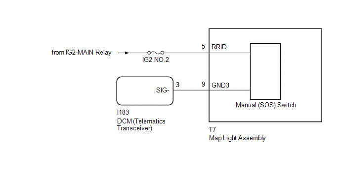
| 1. | CHECK HARNESS AND CONNECTOR (MAP LIGHT ASSEMBLY POWER SOURCE) |
(a) Disconnect the I183 DCM (telematics transceiver) connector.
(b) Disconnect the T7 map light assembly connector.
(c) Measure the voltage according to the value(s) in the table below.
Standard Voltage:
| Tester Connection | Switch Condition | Specified Condition |
|---|---|---|
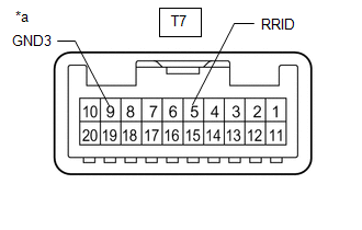
| T7-5 (RRID) - Body Ground | Power switch on (IG) | 11 to 14 V |
(d) Measure the resistance according to the value(s) in the table below.
Standard Resistance:
| Tester Connection | Condition | Specified Condition |
|---|---|---|
| I183-3 (SIG-) - T7-9 (GND3) | Always | Below 1 Ω |
| I183-3 (SIG-) or T7-9 (GND3) - Body ground | Always | 10 kΩ or higher |
| NG | .gif) | REPAIR OR REPLACE HARNESS OR CONNECTOR |
|
.gif)
| 2. | INSPECT MAP LIGHT ASSEMBLY (MANUAL [SOS] SWITCH) |
| (a) Remove the map light assembly. Click here |
|
(b) Apply battery voltage to the connector and check that the manual (SOS) switch illumination comes on.
OK:
| Measurement Condition | Condition | Specified Condition |
|---|---|---|
| Battery positive (+) → T7-5 (RRID) Battery negative (-) → T7-9 (GND3) | Always | Manual (SOS) switch illumination comes on |
| NG | | REPLACE MAP LIGHT ASSEMBLY (MANUAL [SOS] SWITCH) |
|
| 3. | REPLACE DCM (TELEMATICS TRANSCEIVER) |
(a) Replace the DCM (telematics transceiver).
Click here
NOTICE:
- The power switch must be off.
- Do not exchange the DCM (telematics transceiver) with one from another vehicle.
| NEXT | | PERFORM DCM ACTIVATION |
READ NEXT:
 Telephone And Gps Antenna
ComponentsCOMPONENTS ILLUSTRATION *1 DECK FLOOR BOX LH *2 NO. 3 DECK BOARD SUB-ASSEMBLY *3 REAR DECK FLOOR BOX *4 NEGATIVE AUXILIARY BATTERY TERMINAL N*m (kgf*cm, ft.*lbf):
SEE MORE:
Speaker Circuit (B1360)
DESCRIPTION This DTC is stored when a connection malfunction, such as an open, is detected in the wire harness between the stereo component equalizer assembly and No. 1 speaker assembly with box. DTC No. Detection Item DTC Detection Condition Trouble Area B1360 Speaker Circuit Open
Installation
INSTALLATION PROCEDURE 1. INSTALL SLIDING ROOF HOUSING SUB-ASSEMBLY (a) Temporarily install the sliding roof housing sub-assembly with the 8 bolts and 8 nuts. (b) Tighten the nuts in the order indicated in the illustration. Torque: 8.0 N·m {82 kgf·cm, 71 in·lbf} (c) Insert the sliding roof drai
