Lexus NX: Telephone And Gps Antenna
Lexus NX Service Manual / Audio & Visual & Telematics / Cellular Communication / Telephone And Gps Antenna
Components
COMPONENTS
ILLUSTRATION
.png)
| *1 | DECK FLOOR BOX LH | *2 | NO. 3 DECK BOARD SUB-ASSEMBLY |
| *3 | REAR DECK FLOOR BOX | *4 | NEGATIVE AUXILIARY BATTERY TERMINAL |
.png) | N*m (kgf*cm, ft.*lbf): Specified torque | - | - |
ILLUSTRATION
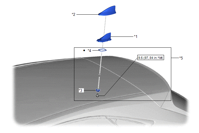
| *1 | TELEPHONE AND GPS ANTENNA (ROOF ANTENNA ASSEMBLY) | *2 | TELEPHONE ANTENNA ASSEMBLY COVER |
| *3 | WASHER AND HOLDER | *4 | SEAL |
| *5 | TELEPHONE ANTENNA HOUSING | - | - |
| | N*m (kgf*cm, ft.*lbf): Specified torque | ● | Non-reusable part |
READ NEXT:
 Parts Location
PARTS LOCATION ILLUSTRATION *1 INNER REAR VIEW MIRROR ASSEMBLY - GARAGE DOOR OPENER *2 INSTRUMENT PANEL JUNCTION BLOCK ASSEMBLY - ECU-IG NO. 3 FUSE *3 NO.1 ENGINE ROOM JUNCTION BLOCK A
SEE MORE:
Data List / Active Test
DATA LIST / ACTIVE TEST DATA LIST HINT: Using the Techstream to read the Data List allows the values or states of switches, sensors, actuators and other items to be read without removing any parts. This non-intrusive inspection can be very useful because intermittent conditions or signals may be dis
Back Camera Disconnected (C1622)
DESCRIPTION This DTC is stored if the radio receiver assembly judges that the signals or signal lines between the television camera assembly and the multi-display assembly are not normal as a result of its self check. DTC No. Detection Item DTC Detection Condition Trouble Area C1622 B
© 2016-2026 Copyright www.lexunx.com
