Lexus NX: Forced Release
Operation Method
OPERATION METHOD
PROCEDURE
1. PARKING BRAKE FORCED RELEASE
NOTICE:
Follow the procedures when using SST to release the parking brake. If the parking brake cannot be released, follow the procedures when not using SST.
(a) When using SST:
(1) Park the vehicle in a safe location, move the shift lever to P, turn the power switch off and chock the wheels.
(2) Remove the No. 2 tool box sub-assembly.
Click here .gif)
(3) Disconnect the parking brake wire assembly connector.
(4) Connect SST (EPB release tool) to SST (sub harness No. 1).
SST: 09756-48020
SST: 09756-48040
(5) Connect SST to the connector of the parking brake wire assembly and auxiliary battery, and then turn on the release button on SST while depressing the brake pedal.
CAUTION:
The vehicle may suddenly move when the parking brake is released. Therefore, use the brake pedal while performing the release operation.
HINT:
- Check the operation noise of the parking brake actuator.
- If there is no operation noise, turn on the release button of SST while forcefully depressing the brake pedal.
- If the battery voltage is low, the parking brake may not be able to be released. In this case, connect a sufficiently charged battery or new battery, and then perform the release operation again.
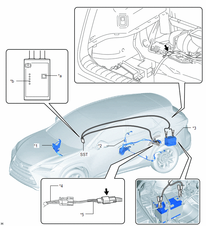
| *1 | BRAKE PEDAL ASSEMBLY | *2 | PARKING BRAKE WIRE ASSEMBLY |
| *3 | AUXILIARY BATTERY | *4 | SST (EPB Release Tool) |
| *5 | SST (Sub Harness No. 1) | - | - |
| *a | Release Button | *b | FINISHED Light |
.png) | Connector | - | - |
(6) After the FINISHED light illuminates on SST, release the brake pedal.
(7) Move the tires forward and rearward to check that the parking brake is released.
(b) When no t using SST:
(1) Park the vehicle in a safe location, move the shift lever to P, turn the power switch off and chock the wheels.
(2) Remove the rear wheel.
CAUTION:
When performing removal using a jack, do not work on a vehicle supported only by jacks. Be sure to support the vehicle using safety stands.
Click here
| (3) Remove the connector from the parking brake actuator assembly. NOTICE:
|
|
.png)
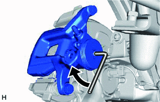
| (4) Using a 5 mm hexagon wrench, remove the 2 bolts and parking brake actuator assembly. NOTICE: The O-ring is a non-reusable part. Replace the O-ring with a new one when installing the parking brake actuator assembly after repairs. |
|
.png)
| (5) Insert a 6 mm hexagon wrench and rotate it clockwise 2 rotations to release the parking brake lock. NOTICE: After releasing the parking brake, install all parts except the connector for the parking brake wire assembly on the interior side, and then move the vehicle. |
|
READ NEXT:
 Parking Brake System
PrecautionPRECAUTION CAUTION: Perform each part replacement carefully, as mistakes could affect the brake system performance and lead to driving problems. When replacing a part, replace with the same
SEE MORE:
USB Audio System Recognition/Play Error
DESCRIPTION When a USB device or "iPod" is connected to the USB jack of the No. 1 stereo jack adapter assembly, it must have playable files. The device must also communicate with and be recognized by the radio receiver assembly. This diagnosis procedure is for when a device is not recognized, or fil
System Description
SYSTEM DESCRIPTION GENERAL (a) In the occupant classification system, the occupant detection ECU calculates the weight of the occupant based on signals from the occupant classification sensors. This system recognizes the occupant as a child if it detects a weight of less than 17 kg (37.4 lb) on the
