Lexus NX: Inside Vehicle
General Maintenance
GENERAL MAINTENANCE
CAUTION / NOTICE / HINT
-
These are maintenance and inspection items that are considered to be the owner's responsibility.
The owner can do them or they can have them done at a service center.
These items include those that should be checked on a daily basis, those that in most cases do not require special tools, and those that are considered to be reasonable for the owner to do.
General maintenance items and procedures are as follows:
PROCEDURE
1. GENERAL NOTES
- Maintenance requirements vary depending on country.
- Check the maintenance schedule in the owner's manual.
- Determine the appropriate time to service the vehicle using either miles driven or time (months) elapsed, whichever reaches the specification first.
- Maintain similar intervals between periodic maintenance unless noted.
- Failing to check each vehicle part could lead to poor engine performance and increased exhaust emissions.
2. LIGHTS
(a) Check that the headlights, stop lights, taillights, turn signal lights, and other lights illuminate or blink properly. Also, check if they have enough brightness.
(b) Check that the headlights are aimed properly.
3. WARNING LIGHTS AND BUZZERS
(a) Check that all the warning lights and buzzers are working.
4. HORNS
(a) Check if the horn is working correctly.
5. WINDSHIELD GLASS
(a) Check for scratches, pits or abrasions.
6. WINDSHIELD WIPER AND WASHER
(a) Check that the washers are aimed properly. Also, check that the washer fluid hits the center of the operating range of each wiper on the windshield.
(b) Check if the wipers streak. Replace them if necessary.
7. WINDSHIELD DEFROSTER
(a) When the air conditioning is on the defroster setting, check that air comes out of the defroster outlets.
8. REAR VIEW MIRROR
(a) Check that the rear view mirror is securely mounted.
9. SUN VISORS
(a) Check that the sun visors move freely and are securely mounted.
10. STEERING WHEEL
(a) Check that the steering wheel has the proper amount of free play. Also check for steering difficulty and unusual noises.
11. SEATS
(a) Check that the seat adjusters, seatback recliner and other seat controls operate smoothly.
(b) Check that all the latches lock securely in all positions.
(c) Check that the locks hold securely in all positions.
(d) Check that the headrests move up and down smoothly and that the locks hold securely in all latched positions.
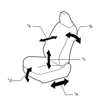
(e) Check the basic function.
| (1) Operate the power seat switches and check that the following seat functions operate properly:
|
|
(2) Operate the rear power seat switch, No. 1 fold seat switch assembly and No. 2 fold seat switch assembly and check that each switch function operates normally.
- Reclining operation (rear power seat switch)
- Fold operation (rear power seat switch, No. 1 fold seat switch assembly and No. 2 fold seat switch assembly)
- Return operation (rear power seat switch, No. 1 fold seat switch assembly and No. 2 fold seat switch assembly)
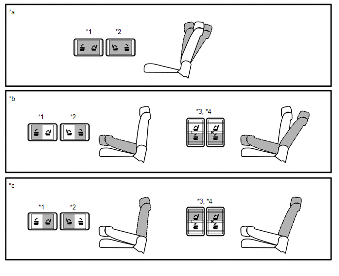
| *1 | Rear Power Seat Switch (Rear Left Seat) | *2 | Rear Power Seat Switch (Rear Right Seat) |
| *3 | No. 1 Fold Seat Switch Assembly | *4 | No. 2 Fold Seat Switch Assembly |
| *a | Reclining Operation | *b | Fold Operation |
| *c | Return Operation | - | - |
12. SEAT BELTS
(a) Check that the seat belt components, such as the buckles, retractors and anchors, operate properly and smoothly.
(b) Check that the belt webbing is not cut, frayed, worn or damaged.
13. ACCELERATOR PEDAL
(a) Check that the pedal operates smoothly. Check that the pedal does not have uneven resistance or stick in certain positions.
14. BRAKE PEDAL
(a) Check that the brake pedal operates smoothly.
(b) Check that the pedal has the proper reserve distance and free play.
(c) Turn the power switch on (READY) and check the brake system indicator.
15. BRAKES
(a) In a safe place, check that the vehicle does not pull or lead to the side when applying the brakes.
16. PARKING BRAKE
(a) Turn the power switch on (READY) and move the shift lever to D. Then depress the brake pedal and pull the parking brake switch (integration control and panel assembly) to the lock side for 1 second. Check the parking brake indicator light (red) condition.
(b) Release the brake pedal and check that the vehicle does not move.
(c) Depress the brake pedal and push the parking brake switch (integration control and panel assembly) to the release side for 1 second. Check the parking brake indicator light (red) condition.
(d) Release the brake pedal and check that the vehicle moves.
17. HYBRID TRANSAXLE "PARK" MECHANISM
(a) Check the lock release button of the shift lever for proper and smooth operation.
(b) Check the shift lever for proper and smooth operation.
(c) When the shift lever is in P and all brakes are released in an area that has a slight grade, check that the vehicle is stable.
18. FLOOR MATS
(a) Check that the correct floor mats are used, and that they are properly installed.
READ NEXT:
 Outside Vehicle
General MaintenanceGENERAL MAINTENANCE CAUTION / NOTICE / HINT
These are maintenance and inspection items that are considered to be the owner's responsibility.
The owner can do them or they can ha
Under Hood
General MaintenanceGENERAL MAINTENANCE PROCEDURE 1. GENERAL NOTES
Maintenance requirements vary depending on country.
Check the maintenance schedule in the owner's manual.
Following the mainte
SEE MORE:
Removal
REMOVAL PROCEDURE 1. PRECAUTION NOTICE: After turning the power switch off, there may be a waiting time before disconnecting the negative (-) auxiliary battery terminal. Click here 2. REMOVE NO. 3 DECK BOARD SUB-ASSEMBLY Click here 3. REMOVE REAR DECK FLOOR BOX Click here 4. REMOVE DECK FLOOR
Front Right Center Sensor (C1AE3)
DESCRIPTION The front center ultrasonic sensor (FRC sensor) is installed to the front bumper. The clearance warning ECU assembly detects obstacles based on signals received from the front center ultrasonic sensor (FRC sensor). If the front center ultrasonic sensor (FRC sensor) has an open circuit or
