- - SLIDING ROOF ECU
- - SLIDE MOTOR
Lexus NX: Parts Location
Lexus NX Service Manual / Vehicle Exterior / Sliding Roof / Convertible / Sliding Roof System / Parts Location
PARTS LOCATION
ILLUSTRATION
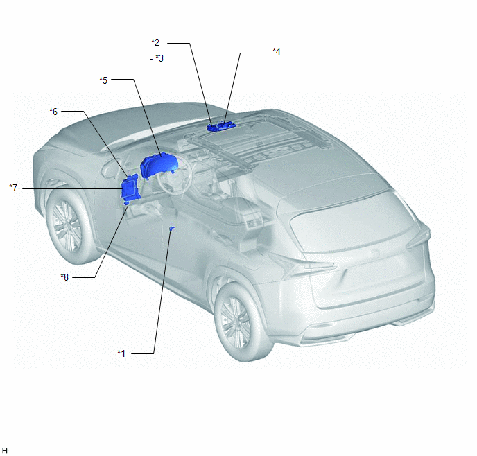
| *1 | FRONT DOOR COURTESY LIGHT SWITCH ASSEMBLY LH | *2 | MAP LIGHT ASSEMBLY |
| *3 | SLIDE ROOF SWITCH | *4 | SLIDING ROOF DRIVE GEAR SUB-ASSEMBLY |
| *5 | COMBINATION METER ASSEMBLY | *6 | INSTRUMENT PANEL JUNCTION BLOCK ASSEMBLY
|
| *7 | MAIN BODY ECU (MULTIPLEX NETWORK BODY ECU) | *8 | DLC3 |
READ NEXT:
 System Diagram
SYSTEM DIAGRAM
System Description
SYSTEM DESCRIPTION SLIDING ROOF SYSTEM DESCRIPTION (a) The sliding roof system controls the sliding roof operation using the sliding roof drive gear sub-assembly (sliding roof ECU). Operating the map
How To Proceed With Troubleshooting
CAUTION / NOTICE / HINT HINT:
Use the following procedure to troubleshoot the sliding roof system.
*: Use the Techstream.
PROCEDURE 1. VEHICLE BROUGHT TO WORKSHOP
NEXT
SEE MORE:
Rear Power Window LH Auto Up / Down Function does not Operate with Rear Power Window Switch LH
DESCRIPTION If the manual up and down function operates normally but the auto up and down function does not, then fail-safe mode may be functioning. If power window initialization has not been performed, the auto up and down function will not operate. Click here WIRING DIAGRAM CAUTION / NOTICE /
Installation
INSTALLATION PROCEDURE 1. INSTALL WINDSHIELD WIPER SWITCH ASSEMBLY (a) Attach the claw to install the windshield wiper switch assembly. (b) Connect each connector. 2. INSTALL UPPER STEERING COLUMN COVER (a) Attach the claw and install the upper steering column cover. (b) Attach the 4 clips and 2 gui
© 2016-2026 Copyright www.lexunx.com
