Lexus NX: Inspection
INSPECTION
PROCEDURE
1. INSPECT BACK DOOR LOCK ASSEMBLY (w/o Power Back Door)
| (a) Check the operation of the door lock motor. (1) Move the back door lock assembly to the lock position. (2) Apply auxiliary battery voltage to the door lock motor assembly and check the operation of the door lock motor. OK:
If the result is not as specified, replace the back door lock assembly. |
|
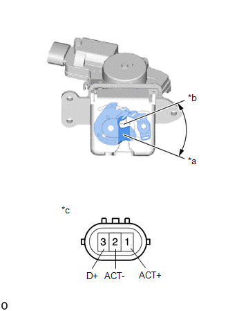
(b) Check the operation of the door courtesy switch.
(1) Measure the resistance according to the value(s) in the table below.
Standard Resistance:
| Tester Connection | Condition | Specified Condition |
|---|---|---|
| 3 (D+) - 2 (ACT-) | Lock | 10 kΩ or higher |
| 3 (D+) - 2 (ACT-) | Unlock | Below 1 Ω |
If the result is not as specified, replace the back door lock assembly.
2. INSPECT BACK DOOR LOCK ASSEMBLY (w/ Power Back Door)
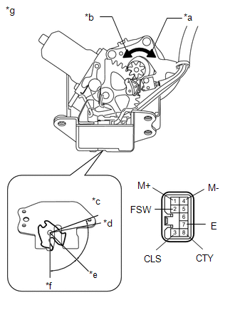
| *a | Clockwise |
| *b | Counterclockwise |
| *c | Over-latch |
| *d | Full-latch |
| *e | Half-latch |
| *f | Open-latch |
| *g | Component without harness connected (Back Door Lock Assembly) |
(a) Apply auxiliary battery voltage to the door lock motor and check the operation of the door lock motor.
OK:| Measurement Condition | Specified Condition |
|---|---|
| Auxiliary battery positive (+) → 1 (M+) Auxiliary battery negative (-) → 4 (M-) | Latch turns to full-latch position (clockwise rotation) |
| Auxiliary battery positive (+) → 4 (M-) Auxiliary battery negative (-) → 1 (M+) | Latch turns to open-latch position (counterclockwise rotation) |
If the result is not as specified, replace the back door lock assembly.
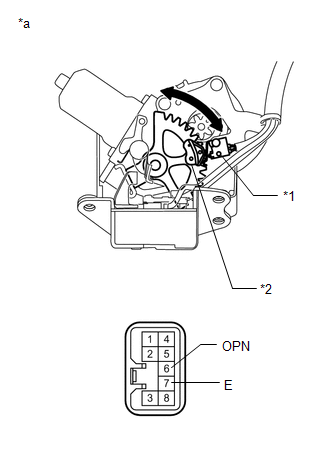
(b) Check the operation of the latch switch.
(1) Measure the resistance according to the value(s) in the table below.
Standard Resistance| Tester Connection | Condition | Specified Condition |
|---|---|---|
| 3 (CLS) - 7 (E) | Open-latch | Below 1 Ω |
| 3 (CLS) - 7 (E) | Open-latch → Half-latch | Below 1 Ω → 10 kΩ or higher |
| 3 (CLS) - 7 (E) | Half-latch | 10 kΩ or higher |
| 3 (CLS) - 7 (E) | Full-latch | 10 kΩ or higher |
| 3 (CLS) - 7 (E) | Over-latch | 10 kΩ or higher → Below 1 Ω → 10 kΩ or higher |
| Tester Connection | Condition | Specified Condition |
|---|---|---|
| 3 (CLS) - 7 (E) | Full-latch | 10 kΩ or higher |
| 3 (CLS) - 7 (E) | Half-latch | 10 kΩ or higher |
| 3 (CLS) - 7 (E) | Half-latch → Open-latch | 10 kΩ or higher → Below 1 Ω |
| 3 (CLS) - 7 (E) | Open-latch | Below 1 Ω |
If the result is not as specified, replace the back door lock assembly.
(c) Check the operation of the pawl switch.
(1) Measure the resistance according to the value(s) in the table below.
Standard Resistance| Tester Connection | Condition | Specified Condition |
|---|---|---|
| 2 (FSW) - 7 (E) | Open-latch | 10 kΩ or higher |
| 2 (FSW) - 7 (E) | Open-latch → Half-latch | 10 kΩ or higher → Below 1 Ω → 10 kΩ or higher |
| 2 (FSW) - 7 (E) | Half-latch | 10 kΩ or higher |
| 2 (FSW) - 7 (E) | Half-latch → Full-latch | 10 kΩ or higher → Below 1 Ω → 10 kΩ or higher |
| 2 (FSW) - 7 (E) | Full-latch | 10 kΩ or higher |
If the result is not as specified, replace the back door lock assembly.
(d) Check the operation of the back door courtesy switch.
(1) Measure the resistance according to the value(s) in the table below.
Standard Resistance| Tester Connection | Condition | Specified Condition |
|---|---|---|
| 8 (CTY) - 7 (E) | Open-latch | Below 1 Ω |
| 8 (CTY) - 7 (E) | Half-latch | Below 1 Ω |
| 8 (CTY) - 7 (E) | Half-latch → Full-latch | Below 1 Ω → 10 kΩ or higher |
| 8 (CTY) - 7 (E) | Full-latch | 10 kΩ or higher |
| 8 (CTY) - 7 (E) | Over-latch | 10 kΩ or higher |
If the result is not as specified, replace the back door lock assembly.
| (e) Check the operation of the selector switch. (1) Measure the resistance according to the value(s) in the table below. Standard Resistance
If the result is not as specified, replace the back door lock assembly. |
|
READ NEXT:
 Installation
INSTALLATION PROCEDURE 1. INSTALL BACK DOOR LOCK ASSEMBLY (w/ Power Back Door) NOTICE:
When installing a new back door lock assembly, if there is any tape stuck to it, remove the tape.
When insta
Components
COMPONENTS ILLUSTRATION *1 DECK FLOOR BOX LH *2 NO. 3 DECK BOARD SUB-ASSEMBLY *3 REAR DECK FLOOR BOX *4 NEGATIVE AUXILIARY BATTERY TERMINAL N*m (kgf*cm, ft.*lbf): Specified
SEE MORE:
Operation Check
OPERATION CHECK CHECK BASIC FUNCTION (a) Operate the rear power seat switch, No. 1 fold seat switch assembly and No. 2 fold seat switch assembly and check that each switch function operates normally.
Reclining operation (rear power seat switch)
Fold operation (rear power seat switch, No. 1 fold
Main Switch Circuit
DESCRIPTION When the blind spot monitor main switch (combination switch assembly) is turned on, a signal is sent to the blind spot monitor sensor LH and the blind spot monitor indicator on the blind spot monitor main switch (combination switch assembly) illuminates. The blind spot monitor system ope
