Lexus NX: Components
COMPONENTS
ILLUSTRATION
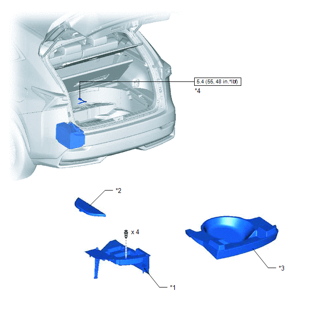
| *1 | DECK FLOOR BOX LH | *2 | NO. 3 DECK BOARD SUB-ASSEMBLY |
| *3 | REAR DECK FLOOR BOX | *4 | NEGATIVE AUXILIARY BATTERY TERMINAL |
.png) | N*m (kgf*cm, ft.*lbf): Specified torque | - | - |
ILLUSTRATION
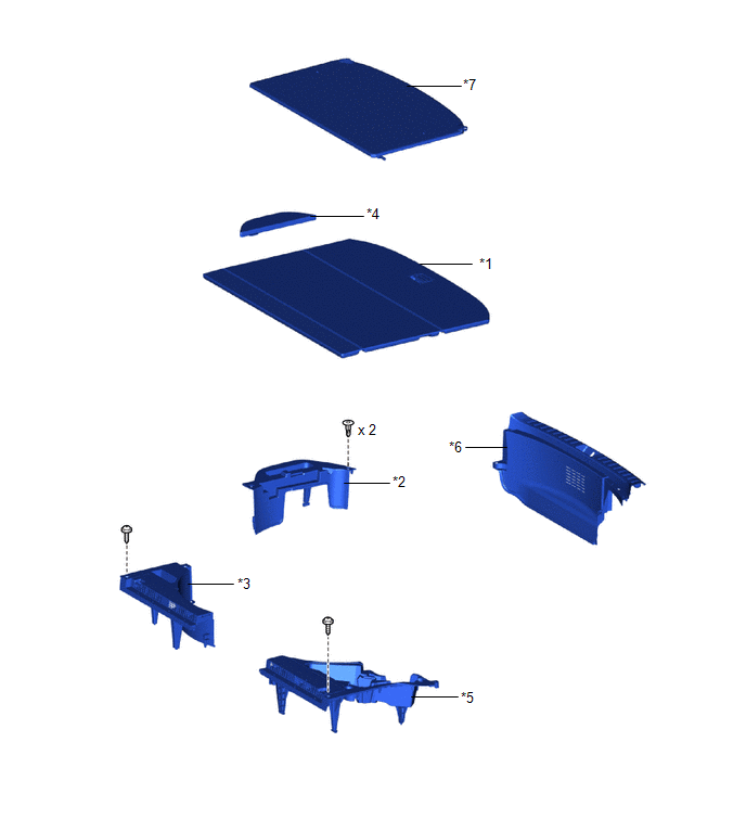
| *1 | DECK BOARD ASSEMBLY | *2 | DECK FLOOR BOX RH |
| *3 | NO. 1 TOOL BOX SUB-ASSEMBLY | *4 | NO. 2 DECK BOARD SUB-ASSEMBLY |
| *5 | NO. 2 TOOL BOX SUB-ASSEMBLY | *6 | REAR FLOOR FINISH PLATE |
| *7 | TONNEAU COVER ASSEMBLY | - | - |
ILLUSTRATION
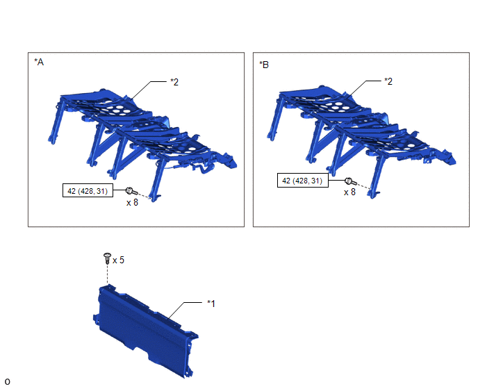
| *A | for Power Seat | - | - |
| *1 | BATTERY SERVICE COVER BOARD | *2 | NO. 1 SEAT LEG ASSEMBLY |
| | N*m (kgf*cm, ft.*lbf): Specified torque | - | - |
ILLUSTRATION
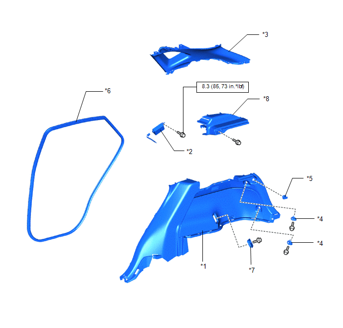
| *1 | DECK TRIM SIDE PANEL ASSEMBLY RH | *2 | ELECTRICAL KEY AND TPMS RECEIVER ASSEMBLY |
| *3 | INNER ROOF SIDE GARNISH ASSEMBLY RH | *4 | LUGGAGE HOLD BELT STRIKER ASSEMBLY |
| *5 | NO. 1 LUGGAGE COMPARTMENT TRIM HOOK | *6 | REAR DOOR OPENING TRIM WEATHERSTRIP RH |
| *7 | ROPE HOOK ASSEMBLY | *8 | UPPER DECK TRIM SIDE BOARD RH |
| | N*m (kgf*cm, ft.*lbf): Specified torque | - | - |
READ NEXT:
 Removal
REMOVAL PROCEDURE 1. PRECAUTION NOTICE: After turning the power switch off, waiting time may be required before disconnecting the cable from the negative (-) auxiliary battery terminal. Click here 2
Installation
INSTALLATION CAUTION / NOTICE / HINT HINT: A bolt without a torque specification is shown in the standard bolt chart. Click here PROCEDURE 1. INSTALL ELECTRICAL KEY AND TPMS RECEIVER ASSEMBLY (a) Co
Door Control Switch
ComponentsCOMPONENTS ILLUSTRATION *1 DOOR CONTROL SWITCH ASSEMBLY *2 POWER WINDOW REGULATOR SWITCH ASSEMBLY WITH FRONT DOOR ARMREST BASE PANEL *3 FRONT DOOR ARMREST BASE PANEL - -
SEE MORE:
Back Door Entry Lock and Unlock Functions do not Operate
DESCRIPTION If the entry lock and unlock functions do not operate for the back door only, the request code may not be being transmitted from the back door. If the entry functions for other doors operate properly, communication between the electrical key transmitter sub-assembly and door control rece
Initialization
INITIALIZATION MAINTENANCE REQUIRED REMINDER RESET PROCEDURE (with mph units) (a) Turn the power switch on (IG). (b) Using the steering pad switch assembly, display the setting display on the multi-information display. (c) Select "Maintenance System" from the setting display and perform initializati
