Lexus NX: Installation
INSTALLATION
CAUTION / NOTICE / HINT
HINT:
- Use the same procedure for the RH and LH sides.
- The procedure listed below is for the LH side.
PROCEDURE
1. INSTALL REAR UPPER COIL SPRING INSULATOR LH
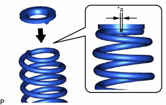
| *a | 10 mm or less |
(a) Install the rear upper coil spring insulator to the rear coil spring.
NOTICE:
Install the rear upper coil insulator so that the distance between the stopper and upper end of the rear coil spring is 10 mm (0.394 in.) or less.
2. INSTALL REAR LOWER COIL SPRING INSULATOR LH
(a) Install the rear lower coil spring insulator to the rear No. 2 suspension arm.
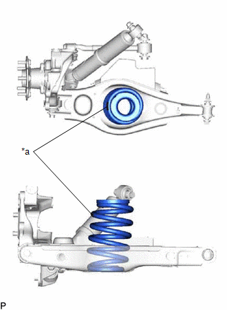
3. INSTALL REAR COIL SPRING LH
| (a) Install the rear coil spring to the rear No. 2 suspension arm. NOTICE: Install the rear coil spring so that the identification marks are positioned as shown in the illustration. |
|
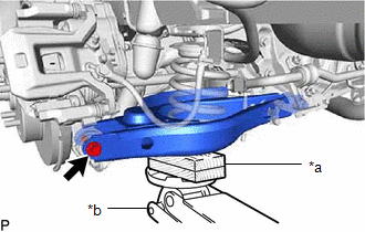
| (b) Using a jack and wooden block, raise the vehicle gradually to install the rear No. 2 suspension arm to the rear axle carrier. Then temporarily install the bolt. |
|
4. INSTALL REAR STABILIZER LINK ASSEMBLY LH
Click here .gif)
5. INSTALL REAR HEIGHT CONTROL SENSOR SUB-ASSEMBLY LH
Click here
6. STABILIZE SUSPENSION
Click here
7. TIGHTEN REAR NO. 2 SUSPENSION ARM ASSEMBLY LH
Click here
8. INSTALL REAR SUSPENSION ARM COVER LH
Click here
9. INSTALL REAR WHEEL
Click here
10. INSPECT AND ADJUST REAR WHEEL ALIGNMENT
Click here
11. HEIGHT CONTROL SENSOR SIGNAL INITIALIZATION
Click here
12. PERFORM INITIALIZATION
Click here
READ NEXT:
 Components
COMPONENTS ILLUSTRATION *A w/ AVS - - *1 REAR NO. 1 SUSPENSION ARM ASSEMBLY LH *2 REAR SHOCK ABSORBER ASSEMBLY LH *3 REAR SUSPENSION TOE ADJUST CAM SUB-ASSEMBLY *4 NO. 2
Removal
REMOVAL CAUTION / NOTICE / HINT HINT:
Use the same procedure for the RH and LH sides.
The procedure listed below is for the LH side.
PROCEDURE 1. REMOVE REAR WHEEL Click here 2. REMOVE REAR
SEE MORE:
Dtc Check / Clear
DTC CHECK / CLEAR CHECK DTC (a) Connect the Techstream to the DLC3. (b) Turn the power switch on (IG). (c) Turn the Techstream on. (d) Enter the following menus: Body Electrical / Telematics / Trouble Codes. Body Electrical > Telematics > Trouble Codes (e) Check for DTCs. Click here CLEAR DT
Inspection
INSPECTION PROCEDURE 1. INSPECT NAVIGATION ANTENNA ASSEMBLY (a) Measure the resistance according to the value(s) in the table below. Standard Resistance: Tester Antenna Tester Connection Condition Specified Condition Navigation antenna 1 - 2 Always 50 to 500 Ω LTE sub-ann
