Lexus NX: Components
COMPONENTS
ILLUSTRATION
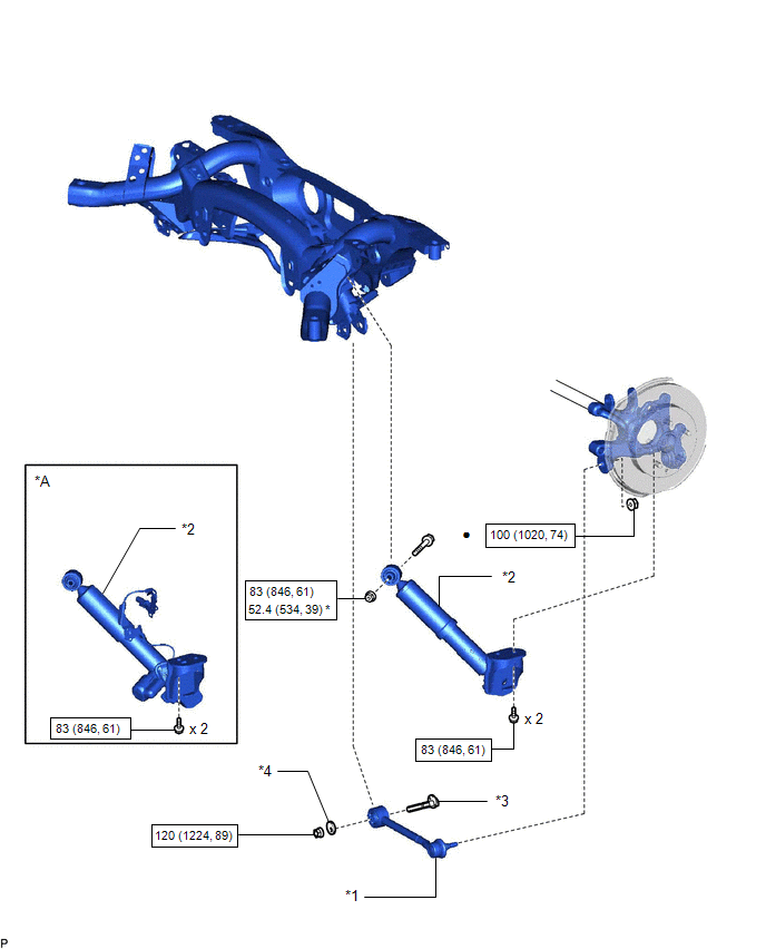
| *A | w/ AVS | - | - |
| *1 | REAR NO. 1 SUSPENSION ARM ASSEMBLY LH | *2 | REAR SHOCK ABSORBER ASSEMBLY LH |
| *3 | REAR SUSPENSION TOE ADJUST CAM SUB-ASSEMBLY | *4 | NO. 2 CAMBER ADJUST CAM |
.png) | N*m (kgf*cm, ft.*lbf): Specified torque | ● | Non-reusable part |
| * | For use with ball joint lock nut wrench | - | - |
ILLUSTRATION
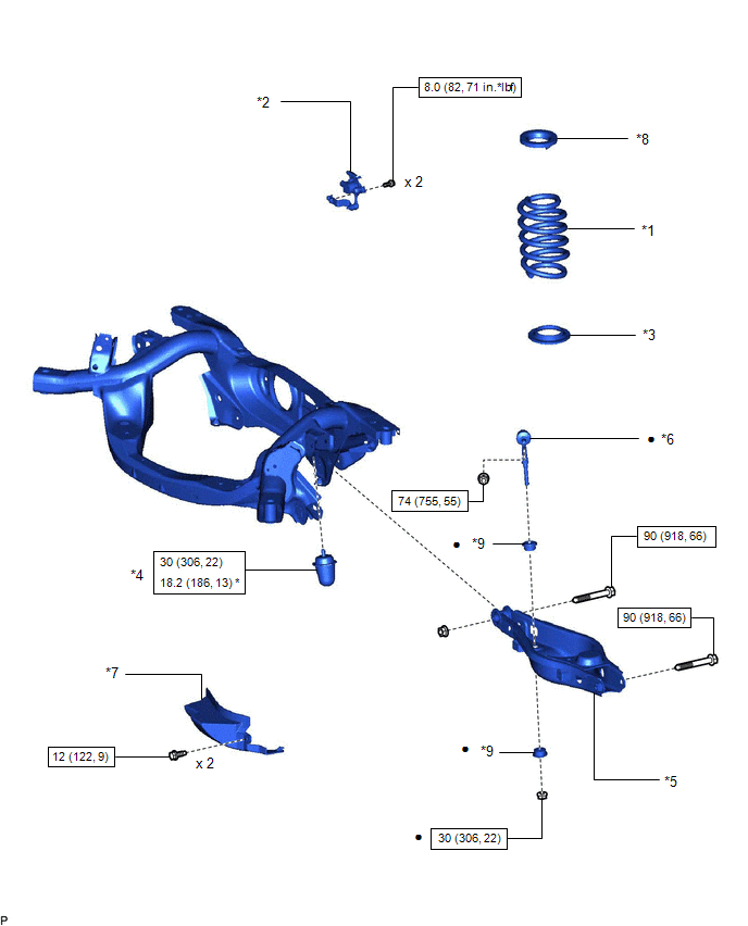
| *1 | REAR COIL SPRING LH | *2 | REAR HEIGHT CONTROL SENSOR SUB-ASSEMBLY LH |
| *3 | REAR LOWER COIL SPRING INSULATOR LH | *4 | REAR NO. 1 SPRING BUMPER LH |
| *5 | REAR NO. 2 SUSPENSION ARM ASSEMBLY LH | *6 | REAR STABILIZER LINK ASSEMBLY LH |
| *7 | REAR SUSPENSION ARM COVER LH | *8 | REAR UPPER COIL SPRING INSULATOR LH |
| *9 | REAR STABILIZER CUSHION | - | - |
| | N*m (kgf*cm, ft.*lbf): Specified torque | * | For use with SST |
| ● | Non-reusable part | - | - |
READ NEXT:
 Removal
REMOVAL CAUTION / NOTICE / HINT HINT:
Use the same procedure for the RH and LH sides.
The procedure listed below is for the LH side.
PROCEDURE 1. REMOVE REAR WHEEL Click here 2. REMOVE REAR
Inspection
INSPECTION CAUTION / NOTICE / HINT HINT:
Use the same procedure for the RH and LH sides.
The procedure listed below is for the LH side.
PROCEDURE 1. INSPECT REAR NO. 1 SUSPENSION ARM ASSEMBLY
Installation
INSTALLATION CAUTION / NOTICE / HINT HINT:
Use the same procedure for the RH and LH sides.
The procedure listed below is for the LH side.
PROCEDURE 1. INSTALL REAR NO. 1 SPRING BUMPER LH (a
SEE MORE:
How To Proceed With Troubleshooting
CAUTION / NOTICE / HINT HINT:
Before performing troubleshooting for the dynamic radar cruise control system, perform troubleshooting for the pre-collision system.
Click here
*: Use the Techstream.
PROCEDURE 1. VEHICLE BROUGHT TO WORKSHOP
NEXT 2. PRE-CHECK
Air Conditioner ECU Vehicle Information Reading/Writing Processor Malfunction (B15F5)
DESCRIPTION This DTC is stored when items controlled by the air conditioning amplifier assembly cannot be customized via the audio and visual system vehicle customization screen. HINT: The air conditioning amplifier assembly controls the air conditioning system related items that are customizable vi
© 2016-2026 Copyright www.lexunx.com
