Lexus NX: Installation
INSTALLATION
PROCEDURE
1. INSTALL MOBILEPHONE BATTERY
CAUTION:
- Do not reuse dropped or damaged parts.
- Wear gloves when contacting parts that have been dropped from a height of 1 m or higher.
- There may be an internal short or the temperature may increase to 100°C or higher due to the shock from being dropped.
- If an internal short has occurred, gas may be discharged. Therefore, if there is even a small amount of heat, maintain a distance of 3 m or more from the vehicle and wait for 1 minute or longer.
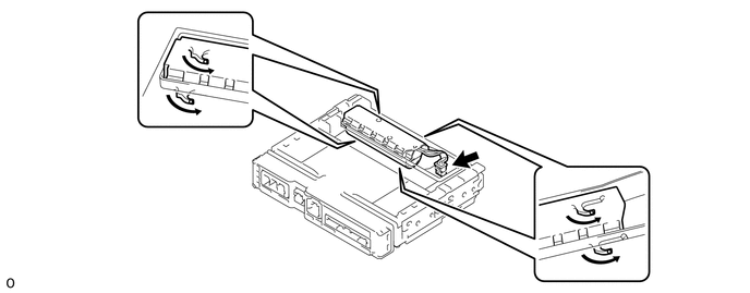
(a) Connect the connector and install the mobilephone battery as shown in the illustration.
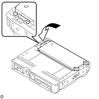
2. INSTALL TRANSCEIVER COVER
| (a) Insert the 2 guides and attach the 2 claws to install the transceiver cover as shown in the illustration. |
|
3. INSTALL DCM (TELEMATICS TRANSCEIVER)
Click here
4. CONNECT CABLE TO NEGATIVE AUXILIARY BATTERY TERMINAL
5. INITIALIZATION AFTER RECONNECTING AUXILIARY BATTERY TERMINAL
Click here .gif)
HINT:
When disconnecting and reconnecting the auxiliary battery, there is an automatic learning function that completes learning when the respective system is used.
Click here
6. PERFORM REGISTRATION
Click here
7. CHECK SRS WARNING LIGHT
Click here
8. INSTALL DECK FLOOR BOX LH
Click here
9. INSTALL REAR DECK FLOOR BOX
Click here
10. INSTALL NO. 3 DECK BOARD SUB-ASSEMBLY
Click here
11. INSTALL DECK BOARD ASSEMBLY
Click here
READ NEXT:
 Precaution
PRECAUTION WHEN DISCONNECTING AUXILIARY BATTERY CABLE NOTICE:
After turning the power switch off, waiting time may be required before disconnecting the cable from the negative (-) auxiliary battery
Parts Location
PARTS LOCATION ILLUSTRATION *A w/o Navigation System *B w/ Navigation System *1 FRONT NO. 1 SPEAKER ASSEMBLY RH *2 FRONT NO. 2 SPEAKER ASSEMBLY RH *3 TELEPHONE MICROPHONE ASS
SEE MORE:
Components
COMPONENTS ILLUSTRATION *A for 8 Inch Display *B for 10.3 Inch Display *1 CENTER INSTRUMENT CLUSTER FINISH PANEL ASSEMBLY *2 CONSOLE ARMREST ASSEMBLY *3 INSTRUMENT PANEL FINISH PLATE *4 INSTRUMENT SIDE PANEL LH *5 INSTRUMENT SIDE PANEL RH *6 LOWER NO. 1 INSTRU
Disassembly
DISASSEMBLY CAUTION / NOTICE / HINT NOTICE:
When using a vise, place aluminum plates between the part and vise.
When using a vise, do not overtighten it.
PROCEDURE 1. REMOVE STEERING LOCK ACTUATOR ASSEMBLY (a) Secure the electric power steering column sub-assembly in a vise. (b) Using a cent
