- Power switch on (READY)
- Driving module switch assembly (ECO mode switch) off
- Temperature settings: MAX HOT
- Ambient temperature: 10°C (50°F) or lower
- Engine coolant temperature: 64°C (147°F) or lower
- IDH terminal signal less than 1 V (Inverter with converter assembly overload not detected)
- Blower switch: LO
Lexus NX: Terminals Of Ecu
Lexus NX Service Manual / Vehicle Interior / Heating / Air Conditioning / Air Conditioning System / Terminals Of Ecu
TERMINALS OF ECU
AIR CONDITIONING AMPLIFIER ASSEMBLY
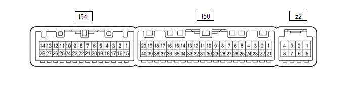
(a) Disconnect the I50 air conditioning amplifier assembly connector.
(b) Measure the resistance and voltage according to the value(s) in the table below.
HINT:
Check from the rear of the connector while it is connected to the air conditioning amplifier assembly.
| Terminal No. (Symbol) | Wiring Color | Terminal Description | Condition | Specified Condition |
|---|---|---|---|---|
| I50-1 (IG+) - Body ground | SB - Body ground | Power source (IG) | Power switch on (IG) | 11 to 14 V |
| Power switch off | Below 1 V | |||
| I50-14 (GND) - Body ground | W-B - Body ground | Ground for main power supply | Always | Below 1 Ω |
| I50-21 (B) - Body ground | GR - Body ground | Power source (Back-up) | Power switch off | 11 to 14 V |
(c) Reconnect the I50 air conditioning amplifier assembly connector.
(d) Measure the resistance, voltage and waveform according to the value(s) in the table below.
HINT:
Check from the rear of the connector while it is connected to the air conditioning amplifier assembly.
| Terminal No. (Symbol) | Wiring Color | Terminal Description | Condition | Specified Condition |
|---|---|---|---|---|
|
*1: Use a thermometer to detect the ambient temperature of the installation area around the thermistor assembly (ambient temperature sensor).
*2: w/ Humidity Sensor | ||||
| I50-3 (PTC2) - I50-14 (GND) | GR - W-B | Quick heater assembly operation signal | | Below 1 V |
| 11 to 14 V | |||
| I50-4 (ECOS) - Body ground | R - Body ground | Integration control and panel assembly (ECO mode switch) signal | Power switch on (IG) Integration control and panel assembly (ECO mode switch) on | Below 1 V |
| Power switch on (IG) Integration control and panel assembly (ECO mode switch) off | 11 to 14 V | |||
| I50-5 (TAM) - I50-13 (SG-2)*1 | L - G | Ambient temperature sensor signal | Power switch on (IG) (do not start the engine and electric motor) Ambient temperature 10°C (50°F) | 1.8 to 2.4 V |
| Power switch on (IG) (do not start the engine and electric motor) Ambient temperature 15°C (59°F) | 1.65 to 2.15 V | |||
| Power switch on (IG) (do not start the engine and electric motor) Ambient temperature 20°C (68°F) | 1.5 to 1.95 V | |||
| Power switch on (IG) (do not start the engine and electric motor) Ambient temperature 25°C (77°F) | 1.35 to 1.75 V | |||
| Power switch on (IG) (do not start the engine and electric motor) Ambient temperature 30°C (86°F) | 1.2 to 1.55 V | |||
| Power switch on (IG) (do not start the engine and electric motor) Ambient temperature 35°C (95°F) | 1.0 to 1.4 V | |||
| Power switch on (IG) (do not start the engine and electric motor) Ambient temperature 40°C (104°F) | 0.85 to 1.25 V | |||
| Power switch on (IG) (do not start the engine and electric motor) Ambient temperature 45°C (113°F) | 0.75 to 1.10 V | |||
| Power switch on (IG) (do not start the engine and electric motor) Ambient temperature 50°C (122°F) | 0.8 to 1.0 V | |||
| I50-6 (TNG) - I50-14 (GND)*2 | GR - W-B | Glass temperature signal |
| 2.2 kΩ |
| I50-7 (TFG) - I50-14 (GND)*2 | V - W-B | Glass surroundings temperature signal |
| 2.2 kΩ |
| I50-9 (PRE) - I50-10 (S5-3) | BE - B | Air conditioner pressure sensor signal | Engine running Air conditioning system operating Refrigerant pressure: Abnormal pressure (higher than 3025 kPa [30.8 kgf/cm2, 439 psi]) | 4.73 V or higher |
| Engine running Air conditioning system operating Refrigerant pressure: Abnormal pressure (below 176 kPa [1.8 kgf/cm2, 26 psi]) | Below 0.62 V | |||
| Engine running Air conditioning system operating Refrigerant pressure: Normal pressure (below 3025 kPa [30.8 kgf/cm2, 439 psi] and higher than 176 kPa [1.8 kgf/cm2, 26 psi]) | 0.62 to 4.73 V | |||
| I50-10 (S5-3) - Body ground | B - Body ground | Ground for air conditioner pressure sensor, ambient temperature sensor, air conditioning lock sensor | Always | Below 1 Ω |
| I50-11 (CANH) | B | CAN communication line | - | - |
| I50-12 (CANL) | W | CAN communication line | - | - |
| I50-13 (SG-2) - Body ground | G - Body ground | Ground for ambient temperature sensor signal | Always | Below 1 Ω |
| I50-19 (PTC3) - I50-14 (GND) | R - W-B | Quick heater assembly operation signal |
| Below 1 V |
| 11 to 14 V | |||
| I50-22 (BLW) - Body ground | R - Body ground | Blower motor speed control signal | Power switch on (IG) Blower switch LO | Pulse generation (See Waveform 1) |
| I50-27 (IDH) - I50-14 (GND) | W - W-B | Inverter with converter assembly current over signal |
| Below 1 V |
| 4.75 to 5.25 V | |||
| I50-28 (RH) - I50-35 (SG-5)*2 | LG - R | Glass humidity sensor signal |
| 2.09 V |
| 2.81 V | |||
| I50-29 (TR) - I50-34 (SG-1) | GR - V | Room temperature sensor signal | Power switch on (IG) Cabin temperature: 25°C (77°F) | 1.8 to 2.2 V |
| Power switch on (IG) Cabin temperature: 40°C (104°F) | 1.2 to 1.6 V | |||
| I50-31 (S5-4) - I50-35 (SG-5)*2 | G - R | Ground for air conditioning thermistor assembly (glass humidity sensor) | Always | Below 1 Ω |
| I50-34 (SG-1) - Body ground | V - Body ground | Ground for room temperature sensor | Always | Below 1 Ω |
| I50-35 (SG-5) - I50-14 (GND)*2 | R - W-B | Ground for air conditioning thermistor assembly | Always | Below 1 Ω |
| I50-37 (LIN1) - Body ground | B - Body ground | LIN communication signal | Power switch on (IG) | Pulse generation |
| I50-40 (PTC1) - I50-14 (GND) | B - W-B | Quick heater assembly operation signal |
| Below 1 V |
| 11 to 14 V | |||
| z2-2 (BUS G) - Body ground | - | Ground for BUS IC | Always | Below 1 V |
| z2-3 (BUS) - z2-2 (BUS G) | - | BUS IC control signal | Power switch on (IG) | Pulse generation (See Waveform 1) |
| z2-4 (B BUS) - z2-2 (BUS G) | - | Power supply for BUS IC | Always | 11 to 14 V |
| z2-5 (SGA) - Body ground | GR - Body ground | Ground for evaporator temperature sensor | Always | Below 1 V |
| z2-6 (TEA) - z2-5 (SGA) | GR - GR | Evaporator temperature sensor signal | Power switch on (IG) Evaporator temperature: 0°C (32°F) | 1.7 to 2.1 V |
| z2-6 (TEA) - z2-5 (SGA) | GR - GR | Evaporator temperature sensor signal | Power switch on (IG) Evaporator temperature: 15°C (59°F) | 0.9 to 1.3 V |
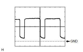
(e) Waveform 1:
| Item | Content |
|---|---|
| Terminal No. | I50-22 (BLW) - Body ground |
| Tool Setting | 1 V/DIV., 500 μs/DIV. |
| Vehicle Condition | Power switch on (IG) Blower switch LO |
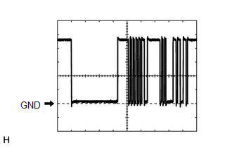
(f) Waveform 2:
| Item | Content |
|---|---|
| Terminal No. | z2-3 (BUS) - z2-2 (BUS G) |
| Tool Setting | 2 V/DIV., 2 ms/DIV. |
| Vehicle Condition | Power switch on (IG) |
AIR CONDITIONING CONTROL ASSEMBLY

(a) Disconnect the I13 air conditioning control assembly connector.
(b) Measure the resistance and voltage according to the value(s) in the table below.
HINT:
Check from the rear of the connector while it is connected to the air conditioning control assembly.
| Terminal No. (Symbol) | Wiring Color | Terminal Description | Condition | Specified Condition |
|---|---|---|---|---|
| I13-8 (IG+) - I13-14 (GND) | LG - W-B | Power source (IG) | Power switch on (IG) | 11 to 14 V |
| Power switch off | Below 1 V | |||
| I13-14 (GND) - Body ground | W-B - Body ground | Ground for center cluster module control assembly | Always | Below 1 Ω |
(c) Reconnect the I13 air conditioning control assembly connector.
(d) Measure the waveform according to the value(s) in the table below.
HINT:
Check from the rear of the connector while it is connected to the air conditioning control assembly.
| Terminal No. (Symbol) | Wiring Color | Terminal Description | Condition | Specified Condition |
|---|---|---|---|---|
| I13-6 (LIN1) - I13-14 (GND) | B - W-B | LIN communication signal | Power switch on (IG) | Pulse generation |
HYBRID VEHCILE CONTROL ECU
Click here .gif)
READ NEXT:
 Check Mode Procedure
CHECK MODE PROCEDURE REFRIGERANT GAS VOLUME CHECK IN NORMAL OPERATION (CHECK A/C SWITCH INDICATOR AND DTC) *a Example (a) Turn the power switch on (READY). (b) Check that A/C switch indicator
Data List / Active Test
DATA LIST / ACTIVE TEST DATA LIST Using the Techstream to read the Data List allows the values or states of switches, sensors, actuators and other items to be read without removing any parts. This non
Diagnostic Trouble Code Chart
DIAGNOSTIC TROUBLE CODE CHART Air Conditioning System DTC No. Detection Item Memory Link B1411 Room Temperature Sensor Circuit Memorized (4 seconds or more) B1412 Ambient T
SEE MORE:
Components
COMPONENTS ILLUSTRATION *1 FRONT DOOR INSIDE HANDLE BEZEL PLUG LH *2 FRONT DOOR TRIM BOARD SUB-ASSEMBLY LH *3 FRONT DOOR TRIM COVER LH *4 OUTER MIRROR INSTALL HOLE COVER LH *5 OUTER REAR VIEW MIRROR ASSEMBLY LH *6 POWER WINDOW REGULATOR MASTER SWITCH ASSEMBLY WITH FRONT
Open in Bus 2 Main Bus Line
DESCRIPTION There may be an open circuit in one of the CAN main bus wire and/or a central gateway ECU (network gateway ECU) branch wire when the resistance between terminals 18 (CA4H) and 17 (CA4L) of the central gateway ECU (network gateway ECU) is 70 Ω or higher. Symptom Trouble Area Res
© 2016-2026 Copyright www.lexunx.com
