Lexus NX: Parts Location
PARTS LOCATION
ILLUSTRATION
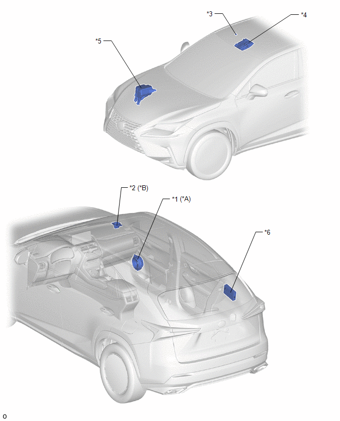
| *A | w/o Navigation System | *B | w/ Navigation System |
| *1 | FRONT NO. 1 SPEAKER ASSEMBLY RH | *2 | FRONT NO. 2 SPEAKER ASSEMBLY RH |
| *3 | TELEPHONE MICROPHONE ASSEMBLY | *4 | MAP LIGHT ASSEMBLY - MANUAL (SOS) SWITCH |
| *5 | NO. 2 ENGINE ROOM RELAY BLOCK - DCM FUSE | *6 | STEREO COMPONENT AMPLIFIER ASSEMBLY |
ILLUSTRATION
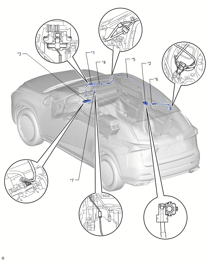
| *1 | TELEPHONE ANTENNA (NAVIGATION ANTENNA ASSEMBLY) | *2 | TELEPHONE AND GPS ANTENNA (ROOF ANTENNA ASSEMBLY) |
| *3 | DCM (TELEMATICS TRANSCEIVER) | *4 | TELEPHONE AND GPS ANTENNA CORD (NO. 1 ANTENNA CORD SUB-ASSEMBLY) |
| *5 | TELEPHONE AND GPS ANTENNA CORD (NO. 2 ANTENNA CORD SUB-ASSEMBLY) | *6 | TELEPHONE AND GPS ANTENNA CORD (NO. 4 ANTENNA CORD SUB-ASSEMBLY) |
| *7 | TELEPHONE ANTENNA CORD (ANTENNA CORD SUB-ASSEMBLY) | - | - |
ILLUSTRATION
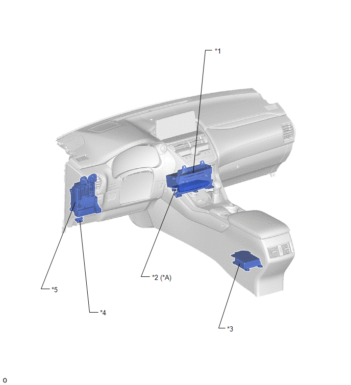
| *A | w/ Navigation System | - | - |
| *1 | RADIO RECEIVER ASSEMBLY | *2 | NAVIGATION ECU |
| *3 | AIRBAG ECU ASSEMBLY | *4 | DLC3 |
| *5 | INSTRUMENT PANEL JUNCTION BLOCK ASSEMBLY - IG2 NO.2 FUSE | - | - |
READ NEXT:
 System Diagram
SYSTEM DIAGRAM
System Description
SYSTEM DESCRIPTION DESCRIPTION (a) Safety Connect performs ACN (Automatic Collision Notification), manual emergency calling, stolen vehicle tracking and roadside assistance service, by audio and data
How To Proceed With Troubleshooting
CAUTION / NOTICE / HINT HINT:
Use the following procedure to troubleshoot the safety connect system.
*: Use the Techstream.
PROCEDURE 1. VEHICLE BROUGHT TO WORKSHOP
NEXT
SEE MORE:
Terminals Of Ecu
TERMINALS OF ECU CHECK FOLD SEAT CONTROL ECU (REAR RIGHT SEAT) (a) Disconnect the h3 and h4 fold seat control ECU (rear right seat) connectors. (b) Measure the resistance and voltage according to the value(s) in the table below. Terminal No. (Symbol) Wiring Color Terminal Description Condi
Components
COMPONENTS ILLUSTRATION *1 DECK TRIM SIDE PANEL ASSEMBLY LH *2 FUEL FILLER OPENING LID LOCK RETAINER *3 FUEL LID WITH MOTOR LOCK ASSEMBLY *4 LUGGAGE HOLD BELT STRIKER ASSEMBLY *5 NO. 1 LUGGAGE COMPARTMENT TRIM HOOK *6 REAR DOOR OPENING TRIM WEATHERSTRIP LH *7 REAR
