Lexus NX: Interior Light Circuit
DESCRIPTION
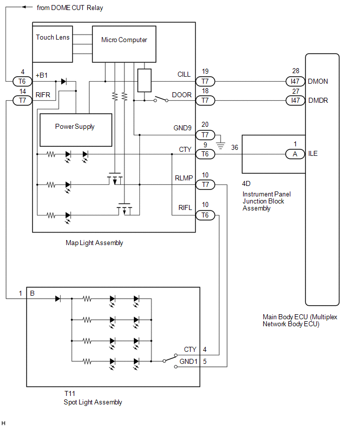
The main body ECU (multiplex network body ECU) controls the map light assembly and spot light assembly.
WIRING DIAGRAM
CAUTION / NOTICE / HINT
NOTICE:
- Recognition code registration is necessary when replacing the main body ECU (multiplex network body ECU).
- If the main body ECU (multiplex network body ECU) is replaced, refer to Registration.
PROCEDURE
| 1. | PERFORM ACTIVE TEST USING TECHSTREAM (ILLUMINATED ENTRY SYSTEM) |
(a) Using the Techstream, perform the Active Test.
Click here .gif)
| Tester Display | Measurement Item | Control Range | Diagnostic Note |
|---|---|---|---|
| Illuminated Entry System | Turns on the lights that are controlled by the illuminated entry system* | ON or OFF | Perform the Active Test with door switch in the map light assembly turned on. |
*: Refer to Description for the lights that are controlled by the illuminated entry system.
Body Electrical > Main Body > Active Test| Tester Display |
|---|
| Illuminated Entry System |
OK:
Map light and spot light comes on.
| OK | .gif) | PROCEED TO NEXT SUSPECTED AREA SHOWN IN PROBLEM SYMPTOMS TABLE |
|
.gif)
| 2. | INSPECT MAP LIGHT ASSEMBLY |
(a) Remove the map light assembly.
Click here
(b) Inspect the map light assembly.
Click here
| NG | | REPLACE MAP LIGHT ASSEMBLY |
|
| 3. | INSPECT SPOT LIGHT ASSEMBLY |
(a) Remove the spot light assembly.
Click here
(b) Inspect the spot light assembly.
Click here
| NG | | REPLACE SPOT LIGHT ASSEMBLY |
|
| 4. | CHECK HARNESS AND CONNECTOR (MAP LIGHT ASSEMBLY - SPOT LIGHT ASSEMBLY) |
(a) Disconnect the T6 and T7 map light assembly connectors.
(b) Disconnect the T11 spot light assembly connector.
(c) Measure the resistance according to the value(s) in the table below.
Standard Resistance:
| Tester Connection | Condition | Specified Condition |
|---|---|---|
| T6-10 (RIFL) - T11-4 (CTY) | Always | Below 1 Ω |
| T7-10 (RLMP) - T11-5 (GND1) | Always | Below 1 Ω |
| T7-14 (RIFR) - T11-1 (B) | Always | Below 1 Ω |
| T6-10 (RIFL) or T11-4 (CTY) - Body ground | Always | 10 kΩ or higher |
| T7-10 (RLMP) or T11-5 (GND1) - Body ground | Always | 10 kΩ or higher |
| T7-14 (RIFR) or T11-1 (B) - Body ground | Always | 10 kΩ or higher |
| NG | | REPAIR OR REPLACE HARNESS OR CONNECTOR |
|
| 5. | INSPECT INSTRUMENT PANEL JUNCTION BLOCK ASSEMBLY |
| (a) Remove the instrument panel junction block assembly. Click here |
|
(b) Remove the main body ECU (multiplex network body ECU) from the instrument panel junction block assembly.
Click here
(c) Measure the resistance according to the value(s) in the table below.
Standard Resistance:
| Tester Connection | Condition | Specified Condition |
|---|---|---|
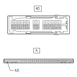
| A-1 (ILE) - 4D-36 | Always | Below 1 Ω |
| OK | | REPLACE MAIN BODY ECU (MULTIPLEX NETWORK BODY ECU) |
| NG | | REPLACE INSTRUMENT PANEL JUNCTION BLOCK ASSEMBLY |
READ NEXT:
 Interior Light Auto Cut Circuit
DESCRIPTION The main body ECU (multiplex network body ECU) controls the DOME CUT relay. WIRING DIAGRAM CAUTION / NOTICE / HINT NOTICE:
Inspect the fuses for circuits related to this system before
Interior Light Switch Signal Circuit
DESCRIPTION The main body ECU (multiplex network body ECU) detects the condition of the door switch and front dome light switch. WIRING DIAGRAM Click here CAUTION / NOTICE / HINT NOTICE:
Recognit
Footwell Light Circuit
DESCRIPTION The main body ECU (multiplex network body ECU) controls the operation of the following lights:
No. 1 interior illumination light assembly LH
No. 1 interior illumination light assembly
SEE MORE:
Rear Sensor Communication Malfunction (C1AED)
DESCRIPTION This DTC is stored when there is an open or short circuit in the communication line between the rear sensors and the ECU, or when there is a malfunction in a rear sensor. DTC No. Detection Item DTC Detection Condition Trouble Area C1AED Rear Sensor Communication Malfunctio
Sending Malfunction (Navigation to APGS) (U0073,U0100,U0129,U0140,U0155,U0164,U0198,U023B,U0265,U0293,U1110)
DESCRIPTION These DTCs are stored when a malfunction occurs in the CAN communication circuit. DTC No. Detection Item DTC Detection Condition Trouble Area U0073 Sending Malfunction (Navigation to APGS) CAN bus connection error CAN communication system U0100 Engine ECU Communi
