Lexus NX: Interior Light Auto Cut Circuit
DESCRIPTION
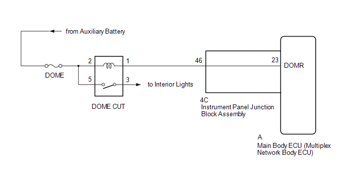
The main body ECU (multiplex network body ECU) controls the DOME CUT relay.
WIRING DIAGRAM
CAUTION / NOTICE / HINT
NOTICE:
- Inspect the fuses for circuits related to this system before performing the following procedure.
- Recognition code registration is necessary when replacing the main body ECU (multiplex network body ECU).
- If the main body ECU (multiplex network body ECU) is replaced, refer to Registration.
PROCEDURE
| 1. | READ VALUE USING TECHSTREAM (RELAY FOR INTERIOR LIGHT AUTO CUT FUNCTION) |
(a) Using the Techstream, read the Data List.
Click here .gif)
| Tester Display | Measurement Item | Control Range | Diagnostic Note |
|---|---|---|---|
| Relay for Interior Light Auto Cut Function | DOME CUT relay | ON or OFF | Check the operation with the interior illumination on. |
| Tester Display |
|---|
| Relay for Interior Light Auto Cut Function |
OK:
Battery saving control (interior light auto cut function) operates.
| OK | .gif) | PROCEED TO NEXT SUSPECTED AREA SHOWN IN PROBLEM SYMPTOMS TABLE |
|
.gif)
| 2. | INSPECT DOME CUT RELAY |
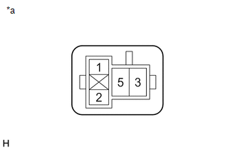
(a) Remove the DOME CUT relay from the No. 3 relay block.
(b) Inspect the DOME CUT relay.
Click here
| NG | | REPLACE DOME CUT RELAY |
|
| 3. | CHECK HARNESS AND CONNECTOR (DOME CUT RELAY - BATTERY) |
| (a) Measure the voltage according to the value(s) in the table below. Standard Voltage:
|
|
| NG | | REPAIR OR REPLACE HARNESS OR CONNECTOR |
|
| 4. | CHECK HARNESS AND CONNECTOR (DOME CUT RELAY - INSTRUMENT PANEL JUNCTION BLOCK ASSEMBLY) |
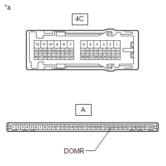
(a) Disconnect the 4C instrument panel junction block assembly connectors.
(b) Measure the resistance according to the value(s) in the table below.
Standard Resistance:
| Tester Connection | Condition | Specified Condition |
|---|---|---|
| DOME CUT relay terminal 1 - 4C-46 | Always | Below 1 Ω |
| DOME CUT relay terminal 1 or 4C-46 - Body ground | Always | 10 kΩ or higher |
| NG | | REPAIR OR REPLACE HARNESS OR CONNECTOR |
|
| 5. | INSPECT INSTRUMENT PANEL JUNCTION BLOCK ASSEMBLY |
| (a) Remove the instrument panel junction block assembly. Click here |
|
(b) Remove the main body ECU (multiplex network body ECU) from the instrument panel junction block assembly.
Click here
(c) Measure the resistance according to the value(s) in the table below.
Standard Resistance:
| Tester Connection | Condition | Specified Condition |
|---|---|---|
| 4C-46 - A-23 (DOMR) | Always | Below 1 Ω |
| OK | | REPLACE MAIN BODY ECU (MULTIPLEX NETWORK BODY ECU) |
| NG | | REPLACE INSTRUMENT PANEL JUNCTION BLOCK ASSEMBLY |
READ NEXT:
 Interior Light Switch Signal Circuit
DESCRIPTION The main body ECU (multiplex network body ECU) detects the condition of the door switch and front dome light switch. WIRING DIAGRAM Click here CAUTION / NOTICE / HINT NOTICE:
Recognit
Footwell Light Circuit
DESCRIPTION The main body ECU (multiplex network body ECU) controls the operation of the following lights:
No. 1 interior illumination light assembly LH
No. 1 interior illumination light assembly
Power Switch Illumination Circuit
DESCRIPTION The illuminated entry system controls the power switch illumination. WIRING DIAGRAM CAUTION / NOTICE / HINT NOTICE:
Recognition code registration is necessary when replacing the main b
SEE MORE:
Front Blower Motor
ComponentsCOMPONENTS ILLUSTRATION *1 BLOWER WITH FAN MOTOR SUB-ASSEMBLY *2 NO. 2 INSTRUMENT PANEL UNDER COVER SUB-ASSEMBLY RemovalREMOVAL PROCEDURE 1. REMOVE NO. 2 INSTRUMENT PANEL UNDER COVER SUB-ASSEMBLY Click here 2. REMOVE BLOWER WITH FAN MOTOR SUB-ASSEMBLY (a) Detach the clam
Power (ignition) switch
Performing the following operations
when carrying the electronic
key on your person starts the hybrid
system or changes power switch
modes.
Starting the hybrid system
1. Check that the parking brake is set.
2. Check that the shift lever is in P.
3. Firmly depress the brake pedal.
and
