Lexus NX: Lost Communication with Side Airbag Sensor RH (B1692,B1693,B1697,B1698)
DESCRIPTION
The circuit for the side collision sensor LH or RH is composed of the airbag ECU assembly, side airbag sensor assembly LH or RH and door side airbag sensor LH or RH.
The side airbag sensor assembly LH or RH and door side airbag sensor LH or RH detect impacts to the vehicle and send signals to the airbag ECU assembly to determine if the airbag should be deployed.
DTC B1692, B1693, B1697 or B1698 is stored when a malfunction is detected in the circuit for the side collision sensor LH or RH.
| DTC No. | Detection Item | DTC Detection Condition | Trouble Area |
|---|---|---|---|
| B1692 | Lost Communication with Side Airbag Sensor RH | One of the following conditions is met:
|
|
| B1693 | Side Airbag Sensor RH Initialization Incomplete | One of the following conditions is met:
|
|
| B1697 | Lost Communication with Side Airbag Sensor LH | One of the following conditions is met:
|
|
| B1698 | Side Airbag Sensor LH Initialization Incomplete | One of the following conditions is met:
|
|
WIRING DIAGRAM
.png)
.png)
CAUTION / NOTICE / HINT
NOTICE:
-
After the power switch is turned off, there may be a waiting time before disconnecting the negative (-) auxiliary battery terminal.
Click here
.gif)
-
When disconnecting and reconnecting the auxiliary battery
Click here
HINT:
When disconnecting and reconnecting the auxiliary battery, there is an automatic learning function that completes learning when the respective system is used.
Click here
-
After replacing the airbag ECU assembly, refer to initialization.
Click here
PROCEDURE
| 1. | CHECK DTC |
(a) Turn the power switch on (IG), and wait for at least 60 seconds.
(b) Clear the DTCs stored in memory.
Click here
(c) Turn the power switch off.
(d) Turn the power switch on (IG), and wait for at least 60 seconds.
(e) Check for DTCs.
Click here
HINT:
Codes other than DTC B1692, B1693, B1697 and B1698 may be output at this time, but they are not related to this check.
| DTC B1692 or B1693 is output | .gif) | GO TO STEP 8 |
| DTC B1692, B1693, B1697 and B1698 are not output | | USE SIMULATION METHOD TO CHECK |
|
.gif)
| 2. | CHECK CONNECTION OF CONNECTORS |
(a) Turn the power switch off.
(b) Disconnect the cable from the negative (-) auxiliary battery terminal, and wait for at least 90 seconds.
(c) Check that the connectors are properly connected to the airbag ECU assembly, side airbag sensor assembly LH and door side airbag sensor LH.
| The connectors are not properly connected | | CONNECT CONNECTORS PROPERLY |
|
| 3. | CHECK CONNECTORS |
(a) Disconnect the connectors from the airbag ECU assembly, side airbag sensor assembly LH and door side airbag sensor LH.
| (b) Check that the connectors (on the airbag ECU assembly side, side airbag sensor assembly LH side and door side airbag sensor LH side) are not damaged. |
|
| The connectors are deformed or damaged | | REPLACE FRONT DOOR WIRE LH OR NO. 2 FLOOR WIRE |
|
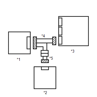
| 4. | CHECK DOOR SIDE AIRBAG SENSOR LH CIRCUIT |
(a) Connect the cable to the negative (-) auxiliary battery terminal, and wait for at least 2 seconds.
| *1 | Door Side Airbag Sensor LH | *2 | Side Airbag Sensor Assembly LH |
| *3 | Connector E | *4 | Connector B |
| *5 | Service Wire | - | - |
| *a | Rear view of wire harness connector (to Door Side Airbag Sensor LH) | *b | Front view of wire harness connector (to Side Airbag Sensor Assembly LH) |
(b) Turn the power switch on (IG).
(c) Measure the voltage according to the value(s) in the table below.
Standard Voltage:
| Tester Connection | Switch Condition | Specified Condition |
|---|---|---|
| Q7-1 (BDL+) - Body ground | Power switch on (IG) | Below 1 V |
| Q7-2 (BDL-) - Body ground | Power switch on (IG) | Below 1 V |
(d) Turn the power switch off.
(e) Disconnect the cable from the negative (-) auxiliary battery terminal, and wait for at least 90 seconds.
(f) Using a service wire, connect terminals 2 (BDL+) and 1 (BDL-) of connector E.
NOTICE:
Do not forcibly insert the service wire into the terminals of the connector when connecting a service wire.
(g) Measure the resistance according to the value(s) in the table below.
Standard Resistance:
| Tester Connection | Condition | Specified Condition |
|---|---|---|
| Q7-1 (BDL+) - Q7-2 (BDL-) | Always | Below 1 Ω |
(h) Disconnect the service wire from connector E.
(i) Measure the resistance according to the value(s) in the table below.
Standard Resistance:
| Tester Connection | Condition | Specified Condition |
|---|---|---|
| Q7-1 (BDL+) - Q7-2 (BDL-) | Always | 1 MΩ or higher |
| Q7-1 (BDL+) - Body ground | Always | 1 MΩ or higher |
| Q7-2 (BDL-) - Body ground | Always | 1 MΩ or higher |
| NG | | GO TO STEP 7 |
|
| 5. | CHECK SIDE AIRBAG SENSOR ASSEMBLY LH |
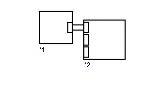
| (a) Connect the connectors to the airbag ECU assembly and door side airbag sensor LH. |
|
.png)
(b) Interchange the side airbag sensor assembly LH with RH and connect the connectors to them.
(c) Connect the cable to the negative (-) auxiliary battery terminal, and wait for at least 2 seconds.
(d) Turn the power switch on (IG), and wait for at least 60 seconds.
(e) Clear the DTCs stored in memory.
Click here
(f) Turn the power switch off.
(g) Turn the power switch on (IG), and wait for at least 60 seconds.
(h) Check for DTCs.
Click here
HINT:
Codes other than DTC B1692, B1693, B1697 and B1698 may be output at this time, but they are not related to this check.
(i) Turn the power switch off.
(j) Disconnect the cable from the negative (-) auxiliary battery terminal, and wait for at least 90 seconds.
(k) Return the side airbag sensor assembly RH and LH to their original positions and connect the connectors to them.
| DTC B1692 or B1693 is output | | REPLACE SIDE AIRBAG SENSOR ASSEMBLY LH |
| DTC B1692, B1693, B1697 and B1698 are not output | | USE SIMULATION METHOD TO CHECK |
|
| 6. | CHECK DOOR SIDE AIRBAG SENSOR LH |
| (a) Interchange the door side airbag sensor LH with RH and connect the connectors to them. |
|
.png)
(b) Connect the cable to the negative (-) auxiliary battery terminal, and wait for at least 2 seconds.
(c) Turn the power switch on (IG), and wait for at least 60 seconds.
(d) Clear the DTCs stored in memory.
Click here
(e) Turn the power switch off.
(f) Turn the power switch on (IG), and wait for at least 60 seconds.
(g) Check for DTCs.
Click here
HINT:
Codes other than DTC B1692, B1693, B1697 and B1698 may be output at this time, but they are not related to this check.
(h) Turn the power switch off.
(i) Disconnect the cable from the negative (-) auxiliary battery terminal, and wait for at least 90 seconds.
(j) Return the door side airbag sensor RH and LH to their original positions and connect the connectors to them.
| DTC B1692 or B1693 is output | | REPLACE DOOR SIDE AIRBAG SENSOR LH |
| DTC B1697 or B1698 is output | | REPLACE AIRBAG ECU ASSEMBLY |
| DTC B1692, B1693, B1697 and B1698 are not output | | USE SIMULATION METHOD TO CHECK |
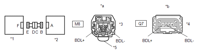
| 7. | CHECK NO. 2 FLOOR WIRE |
(a) Disconnect the No. 2 floor wire connector from the front door wire LH.
| *1 | Door Side Airbag Sensor LH | *2 | Side Airbag Sensor Assembly LH |
| *3 | Front Door Wire LH | *4 | No. 2 Floor Wire |
| *5 | Connector C | *6 | Connector B |
| *7 | Service Wire | - | - |
| *a | Front view of wire harness connector (to Front Door Wire LH) | *b | Front view of wire harness connector (to Side Airbag Sensor Assembly LH) |
(b) Connect the cable to the negative (-) auxiliary battery terminal, and wait for at least 2 seconds.
(c) Turn the power switch on (IG).
(d) Measure the voltage according to the value(s) in the table below.
Standard Voltage:
| Tester Connection | Switch Condition | Specified Condition |
|---|---|---|
| Q7-1 (BDL+) - Body ground | Power switch on (IG) | Below 1 V |
| Q7-2 (BDL-) - Body ground | Power switch on (IG) | Below 1 V |
(e) Turn the power switch off.
(f) Disconnect the cable from the negative (-) auxiliary battery terminal, and wait for at least 90 seconds.
(g) Using a service wire, connect terminals 1 (BDL+) and 2 (BDL-) of connector C.
NOTICE:
Do not forcibly insert the service wire into the terminals of the connector when connecting a service wire.
(h) Measure the resistance according to the value(s) in the table below.
Standard Resistance:
| Tester Connection | Condition | Specified Condition |
|---|---|---|
| Q7-1 (BDL+) - Q7-2 (BDL-) | Always | Below 1 Ω |
(i) Disconnect the service wire from connector C.
(j) Measure the resistance according to the value(s) in the table below.
Standard Resistance:
| Tester Connection | Condition | Specified Condition |
|---|---|---|
| Q7-1 (BDL+) - Q7-2 (BDL-) | Always | 1 MΩ or higher |
| Q7-1 (BDL+) - Body ground | Always | 1 MΩ or higher |
| Q7-2 (BDL-) - Body ground | Always | 1 MΩ or higher |
| OK | | REPLACE FRONT DOOR WIRE LH |
| NG | | REPLACE NO. 2 FLOOR WIRE |
| 8. | CHECK CONNECTION OF CONNECTORS |
(a) Turn the power switch off.
(b) Disconnect the cable from the negative (-) auxiliary battery terminal, and wait for at least 90 seconds.
(c) Check that the connectors are properly connected to the airbag ECU assembly, side airbag sensor assembly RH and door side airbag sensor RH.
| The connectors are not properly connected | | CONNECT CONNECTORS PROPERLY |
|
| 9. | CHECK CONNECTORS |
(a) Disconnect the connectors from the airbag ECU assembly, side airbag sensor assembly RH and door side airbag sensor RH.
| (b) Check that the connectors (on the airbag ECU assembly side, side airbag sensor assembly RH side and door side airbag sensor RH side) are not damaged. |
|
| The connectors are deformed or damaged | | REPLACE FRONT DOOR WIRE RH OR FLOOR WIRE |
|
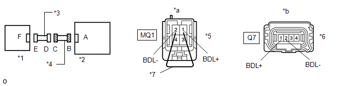
| 10. | CHECK DOOR SIDE AIRBAG SENSOR RH CIRCUIT |
(a) Connect the cable to the negative (-) auxiliary battery terminal, and wait for at least 2 seconds.
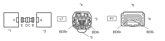
| *1 | Door Side Airbag Sensor RH | *2 | Side Airbag Sensor Assembly RH |
| *3 | Connector E | *4 | Connector B |
| *5 | Service Wire | - | - |
| *a | Rear view of wire harness connector (to Door Side Airbag Sensor RH) | *b | Front view of wire harness connector (to Side Airbag Sensor Assembly RH) |
(b) Turn the power switch on (IG).
(c) Measure the voltage according to the value(s) in the table below.
Standard Voltage:
| Tester Connection | Switch Condition | Specified Condition |
|---|---|---|
| P7-1 (BDR+) - Body ground | Power switch on (IG) | Below 1 V |
| P7-2 (BDR-) - Body ground | Power switch on (IG) | Below 1 V |
(d) Turn the power switch off.
(e) Disconnect the cable from the negative (-) auxiliary battery terminal, and wait for at least 90 seconds.
(f) Using a service wire, connect terminals 2 (BDR+) and 1 (BDR-) of connector E.
NOTICE:
Do not forcibly insert the service wire into the terminals of the connector when connecting a service wire.
(g) Measure the resistance according to the value(s) in the table below.
Standard Resistance:
| Tester Connection | Condition | Specified Condition |
|---|---|---|
| P7-1 (BDR+) - P7-2 (BDR-) | Always | Below 1 Ω |
(h) Disconnect the service wire from connector E.
(i) Measure the resistance according to the value(s) in the table below.
Standard Resistance:
| Tester Connection | Condition | Specified Condition |
|---|---|---|
| P7-1 (BDR+) - P7-2 (BDR-) | Always | 1 MΩ or higher |
| P7-1 (BDR+) - Body ground | Always | 1 MΩ or higher |
| P7-2 (BDR-) - Body ground | Always | 1 MΩ or higher |
| NG | | GO TO STEP 13 |
|
| 11. | CHECK SIDE AIRBAG SENSOR ASSEMBLY RH |
| (a) Connect the connectors to the airbag ECU assembly and door side airbag sensor RH. |
|
(b) Interchange the side airbag sensor assembly RH with LH and connect the connectors to them.
(c) Connect the cable to the negative (-) auxiliary battery terminal, and wait for at least 2 seconds.
(d) Turn the power switch on (IG), and wait for at least 60 seconds.
(e) Clear the DTCs stored in memory.
Click here
(f) Turn the power switch off.
(g) Turn the power switch on (IG), and wait for at least 60 seconds.
(h) Check for DTCs.
Click here
HINT:
Codes other than DTC B1692, B1693, B1697 and B1698 may be output at this time, but they are not related to this check.
(i) Turn the power switch off.
(j) Disconnect the cable from the negative (-) auxiliary battery terminal, and wait for at least 90 seconds.
(k) Return the side airbag sensor assembly LH and RH to their original positions and connect the connectors to them.
| DTC B1697 or B1698 is output | | REPLACE SIDE AIRBAG SENSOR ASSEMBLY RH |
| DTC B1692, B1693, B1697 and B1698 are not output | | USE SIMULATION METHOD TO CHECK |
|
| 12. | CHECK DOOR SIDE AIRBAG SENSOR RH |
| (a) Interchange the door side airbag sensor RH with LH and connect the connectors to them. |
|
(b) Connect the cable to the negative (-) auxiliary battery terminal, and wait for at least 2 seconds.
(c) Turn the power switch on (IG), and wait for at least 60 seconds.
(d) Clear the DTCs stored in memory.
Click here
(e) Turn the power switch off.
(f) Turn the power switch on (IG), and wait for at least 60 seconds.
(g) Check for DTCs.
Click here
HINT:
Codes other than DTC B1692, B1693, B1697 and B1698 may be output at this time, but they are not related to this check.
(h) Turn the power switch off.
(i) Disconnect the cable from the negative (-) auxiliary battery terminal, and wait for at least 90 seconds.
(j) Return the door side airbag sensor LH and RH to their original positions and connect the connectors to them.
| DTC B1697 or B1698 is output | | REPLACE DOOR SIDE AIRBAG SENSOR RH |
| DTC B1692 or B1693 is output | | REPLACE AIRBAG ECU ASSEMBLY |
| DTC B1692, B1693, B1697 and B1698 are not output | | USE SIMULATION METHOD TO CHECK |
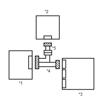
| 13. | CHECK FLOOR WIRE |
(a) Disconnect the floor wire connector from the front door wire RH.
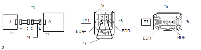
| *1 | Door Side Airbag Sensor RH | *2 | Side Airbag Sensor Assembly RH |
| *3 | Front Door Wire RH | *4 | Floor Wire |
| *5 | Connector C | *6 | Connector B |
| *7 | Service Wire | - | - |
| *a | Front view of wire harness connector (to Front Door Wire RH) | *b | Front view of wire harness connector (to Side Airbag Sensor Assembly RH) |
(b) Connect the cable to the negative (-) auxiliary battery terminal, and wait for at least 2 seconds.
(c) Turn the power switch on (IG).
(d) Measure the voltage according to the value(s) in the table below.
Standard Voltage:
| Tester Connection | Switch Condition | Specified Condition |
|---|---|---|
| P7-1 (BDR+) - Body ground | Power switch on (IG) | Below 1 V |
| P7-2 (BDR-) - Body ground | Power switch on (IG) | Below 1 V |
(e) Turn the power switch off.
(f) Disconnect the cable from the negative (-) auxiliary battery terminal, and wait for at least 90 seconds.
(g) Using a service wire, connect terminals 2 (BDR+) and 1 (BDR-) of connector C.
NOTICE:
Do not forcibly insert the service wire into the terminals of the connector when connecting a service wire.
(h) Measure the resistance according to the value(s) in the table below.
Standard Resistance:
| Tester Connection | Condition | Specified Condition |
|---|---|---|
| P7-1 (BDR+) - P7-2 (BDR-) | Always | Below 1 Ω |
(i) Disconnect the service wire from connector C.
(j) Measure the resistance according to the value(s) in the table below.
Standard Resistance:
| Tester Connection | Condition | Specified Condition |
|---|---|---|
| P7-1 (BDR+) - P7-2 (BDR-) | Always | 1 MΩ or higher |
| P7-1 (BDR+) - Body ground | Always | 1 MΩ or higher |
| P7-2 (BDR-) - Body ground | Always | 1 MΩ or higher |
| OK | | REPLACE FRONT DOOR WIRE RH |
| NG | | REPLACE FLOOR WIRE |
READ NEXT:
 Short in D Squib Circuit (B1800-B1803)
DESCRIPTION The driver side squib circuit consists of the airbag ECU assembly, spiral cable sub-assembly and horn button assembly. The circuit instructs the SRS to deploy when deployment conditions ar
Short in P Squib Circuit (B1805-B1808)
DESCRIPTION The front passenger side squib circuit consists of the airbag ECU assembly and instrument panel passenger airbag assembly. The circuit instructs the SRS to deploy when deployment condition
Short in D Squib (Dual Stage - 2nd Step) Circuit (B1810-B1813)
DESCRIPTION The driver side squib 2nd step circuit consists of the airbag ECU assembly, spiral cable sub-assembly and horn button assembly. The circuit instructs the SRS to deploy when deployment cond
SEE MORE:
USB Device Malfunction (B1585)
DESCRIPTION This DTC is stored when a malfunction occurs in a connected device. DTC No. Detection Item DTC Detection Condition Trouble Area B1585 USB Device Malfunction When one of the conditions below is met:
A non mass-storage class or incompatible protocol USB device is connec
How To Proceed With Troubleshooting
CAUTION / NOTICE / HINT HINT:
Before troubleshooting the front camera system, first refer to How to Proceed with Troubleshooting for the pre-collision system.
Click here
If a message is displayed on the multi-information display, refer to How to Proceed with Troubleshooting for the pre-collis
