-
Communication stop for "Main Body" is indicated on the "Communication Bus Check" screen of the Techstream.
Click here
.gif)
-
Communication system DTCs (DTCs that start with U) that correspond to "Main Body ECU Communication Stop Mode" in "DTC Combination Table" are output.
Click here
Lexus NX: Main Body ECU Communication Stop Mode
Lexus NX Service Manual / Power Source & Network / Networking / Can Communication System / Main Body ECU Communication Stop Mode
DESCRIPTION
| Detection Item | Symptom | Trouble Area |
|---|---|---|
| Main Body ECU Communication Stop Mode | Any of the following conditions are met: |
|
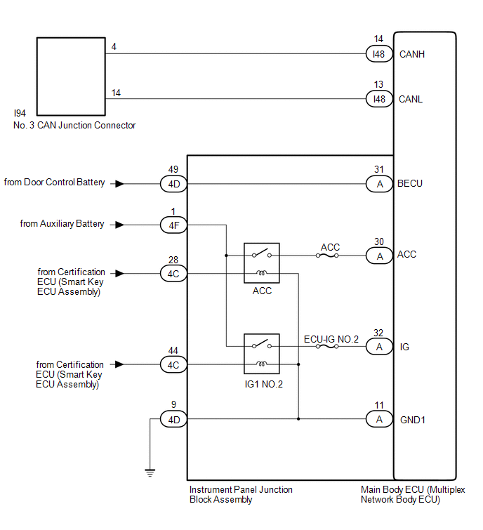
WIRING DIAGRAM
CAUTION / NOTICE / HINT
CAUTION:
When performing the confirmation driving pattern, obey all speed limits and traffic laws.
NOTICE:
- Inspect the fuses for circuits related to this system before performing the following procedure.
- Before measuring the resistance of the CAN bus, turn the power switch off and leave the vehicle for 1 minute or more without operating the key or any switches, or opening or closing the doors. After that, disconnect the cable from the negative (-) auxiliary battery terminal and leave the vehicle for 1 minute or more before measuring the resistance.
-
After turning the power switch off, waiting time may be required before disconnecting the cable from the negative (-) auxiliary battery terminal.
Click here
-
When disconnecting and reconnecting the auxiliary battery.
Click here
HINT:
When disconnecting and reconnecting the auxiliary battery, there is an automatic learning function that completes learning when the respective system is used.
Click here
-
Some parts must be initialized and set when replacing or removing and installing parts.
Click here
-
Because the order of diagnosis is important to allow correct diagnosis, make sure to begin troubleshooting using How to Proceed with Troubleshooting when CAN communication system related DTCs are output.
Click here
-
After performing repairs, perform the DTC check procedure and confirm that the DTCs are not output again.
DTC check procedure: Turn the power switch on (IG) and wait for 1 minute or more. Then operate the suspected malfunctioning system and drive the vehicle at 60 km/h (37 mph) or more for 5 minutes or more.
-
After the repair, perform the CAN bus check and check that all the ECUs and sensors connected to the CAN communication system are displayed as normal.
Click here
HINT:
- Operating the power switch, any switches or any doors triggers related ECU and sensor communication with the CAN, which causes resistance variation.
- Even after DTCs are cleared, if a DTC is stored again after driving the vehicle for a while, the malfunction may be occurring due to vibration of the vehicle. In such a case, wiggling the ECUs or wire harness while performing the inspection below may help determine the cause of the malfunction.
PROCEDURE
| 1. | CHECK FOR OPEN IN CAN BUS WIRE (MAIN BODY ECU [MULTIPLEX NETWORK BODY ECU] BRANCH WIRE) |
(a) Disconnect the cable from the negative (-) auxiliary battery terminal.
| (b) Disconnect the main body ECU (multiplex network body ECU) connector. |
|
(c) Measure the resistance according to the value(s) in the table below.
Standard Resistance:
| Tester Connection | Condition | Specified Condition |
|---|---|---|
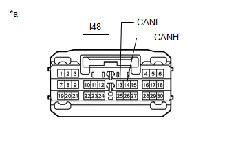
| I48-14 (CANH) - I48-13 (CANL) | Cable disconnected from negative (-) auxiliary battery terminal | 54 to 69 Ω |
| NG | .gif) | REPAIR OR REPLACE CAN BRANCH WIRE OR CONNECTOR |
|
.gif)
| 2. | CHECK HARNESS AND CONNECTOR (POWER SOURCE CIRCUIT) |
| (a) Reconnect the cable to the negative (-) auxiliary battery terminal. |
|
(b) Remove the instrument panel junction block assembly.
Click here
(c) reconnect the instrument panel junction block assembly connectors.
(d) Measure the voltage according to the value(s) in the table below.
Standard Voltage:
| Tester Connection | Switch Condition | Specified Condition |
|---|---|---|
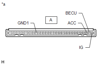
| A-30 (ACC) - Body ground | Power switch on (ACC) | 11 to 14 V |
| Power switch off | Below 1 V | |
| A-31 (BECU) - Body ground | Power switch off | 11 to 14 V |
| A-32 (IG) - Body ground | Power switch on (IG) | 11 to 14 V |
| Power switch off | Below 1 V |
(e) Measure the resistance according to the value(s) in the table below.
Standard Resistance:
| Tester Connection | Condition | Specified Condition |
|---|---|---|
| A-11 (GND1) - Body ground | Always | Below 1 Ω |
| OK | | REPLACE MAIN BODY ECU (MULTIPLEX NETWORK BODY ECU) |
|
| 3. | CHECK HARNESS AND CONNECTOR (POWER SOURCE CIRCUIT) |
(a) Disconnect the instrument panel junction block assembly connectors.
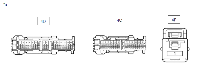
| *a | Front view of wire harness connector (to Instrument Panel Junction Block Assembly) | - | - |
(b) Measure the voltage according to the value(s) in the table below.
Standard Voltage:
| Tester Connection | Switch Condition | Specified Condition |
|---|---|---|
| 4D-49 - Body ground | Power switch off | 11 to 14 V |
| 4F-1 - Body ground | Power switch off | 11 to 14 V |
| 4C-28 - Body ground | Power switch on (ACC) | 11 to 14 V |
| Power switch off | Below 1 V | |
| 4C-44 - Body ground | Power switch on (IG) | 11 to 14 V |
| Power switch off | Below 1 V |
(c) Measure the resistance according to the value(s) in the table below.
Standard Resistance:
| Tester Connection | Condition | Specified Condition |
|---|---|---|
| 4D-9 - Body ground | Always | Below 1 Ω |
| OK | | REPLACE INSTRUMENT PANEL JUNCTION BLOCK ASSEMBLY |
| NG | | REPAIR OR REPLACE HARNESS OR CONNECTOR (POWER SOURCE CIRCUIT) |
READ NEXT:
 Combination Meter ECU Communication Stop Mode
DESCRIPTION Detection Item Symptom Trouble Area Combination Meter ECU Communication Stop Mode Any of the following conditions are met:
Communication stop for "Combination Meter" is ind
Certification ECU Communication Stop Mode
DESCRIPTION Detection Item Symptom Trouble Area Certification ECU Communication Stop Mode Any of the following conditions are met:
Communication stop for "Certification (Smart)" is ind
Center Airbag Sensor Communication Stop Mode
DESCRIPTION Detection Item Symptom Trouble Area Center Airbag Sensor Communication Stop Mode Any of the following conditions are met:
Communication stop for "Airbag" is indicated on th
SEE MORE:
Dtc Check / Clear
DTC CHECK / CLEAR CHECK DTC (a) Connect the Techstream to the DLC3. (b) Turn the power switch on (IG). (c) Turn the intelligent clearance sonar system on. (d) Turn the Techstream on. (e) Enter the following menus: Body Electrical / Advanced Parking Guidance/ICS/Intuitive P/A / Trouble Codes. (f) Che
Check Mode Procedure
CHECK MODE PROCEDURE REFRIGERANT GAS VOLUME CHECK IN NORMAL OPERATION (CHECK A/C SWITCH INDICATOR AND DTC) *a Example (a) Turn the power switch on (READY). (b) Check that A/C switch indicator remains on when the following conditions are met. Measurement Condition Item Condition A/C
© 2016-2026 Copyright www.lexunx.com
