Lexus NX: Open Circuit in Main Relay 1 (C1311,C1312)
DESCRIPTION
The ABS main relay supplies power to the changeover solenoid and the linear solenoid.
The ABS main relay remains on for approximately 2 minutes after the power switch is turned off and the input of brake pedal operation signals stops, and supplies power to the system to keep it ready to operate.
| DTC No. | Detection Item | INF Code | DTC Detection Condition | Trouble Area | Note |
|---|---|---|---|---|---|
| C1311 | Open Circuit in Main Relay 1 | 1 | Either of the following is detected:
|
| - |
| C1312 | Short Circuit in Main Relay 1 | 2 | The ABS main relay contact is turned ON (BS terminal voltage 3.5 V or more) for 4.5 seconds or more when the ABS main relay OFF is requested from the ECU. |
| - |
WIRING DIAGRAM
Refer to DTCs C1241 and C1242.
Click here .gif)
CAUTION / NOTICE / HINT
NOTICE:
-
When replacing the skid control ECU (brake booster with master cylinder assembly), perform initialization and calibration of the linear solenoid valve.
Click here
- Inspect the fuses for circuits related to this system before performing the following procedure.
PROCEDURE
| 1. | PERFORM ACTIVE TEST USING TECHSTREAM (ABS MAIN RELAY) |
(a) Connect the Techstream to the DLC3.
(b) Turn the power switch on (IG).
(c) Select the Active Test on the Techstream.
Click here
| Tester Display | Measurement Item | Control Range | Diagnostic Note |
|---|---|---|---|
| ECB Main Relay | ABS main relay | Relay ON/OFF | ECB: Electronically Controlled Brake System |
| Tester Display |
|---|
| ECB Main Relay |
(d) Select the Data List on the Techstream.
Click here
| Tester Display | Measurement Item | Range | Normal Condition | Diagnostic Note |
|---|---|---|---|---|
| ECB Main Relay | ABS main relay | ON or OFF | ON: Relay on OFF: Relay off | ECB: Electronically Controlled Brake System |
| Tester Display |
|---|
| ECB Main Relay |
(e) Check that the condition of the ABS main relay observed on the Techstream changes according to the Techstream operation.
| Result | Proceed to |
|---|---|
| ABS main relay in the Data List turns ON/OFF using the Active Test. | A |
| ABS main relay in the Data List does not change using the Active Test. | B |
| B | .gif) | GO TO STEP 4 |
|
.gif)
| 2. | CHECK HARNESS AND CONNECTOR (BS TERMINAL) |
| (a) Turn the power switch off. |
|
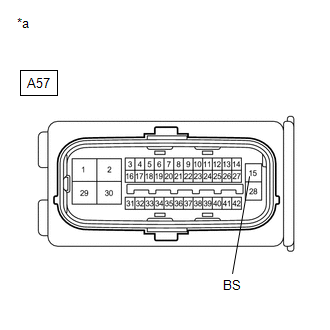
(b) Make sure that there is no looseness at the locking part and the connecting part of the connector.
(c) Disconnect the A57 skid control ECU (brake booster with master cylinder assembly) connector.
(d) Measure the voltage according to the value(s) in the table below.
Standard Voltage:
| Tester Connection | Condition | Specified Condition |
|---|---|---|
| A57-15 (BS) - Body ground | Always | 11 to 14 V |
| NG | | REPAIR OR REPLACE HARNESS OR CONNECTOR (BS CIRCUIT) |
|
| 3. | RECONFIRM DTC |
(a) Reconnect the A57 skid control ECU (brake booster with master cylinder assembly) connector.
(b) Clear the DTCs.
Click here
(c) Turn the power switch off.
(d) Turn the power switch on (IG).
(e) Check if the same DTC is output.
Click here
| Result | Proceed to |
|---|---|
| DTCs C1311 and C1312 are not output. | A |
| DTCs C1311 and/or C1312 are output. | B |
| A | | USE SIMULATION METHOD TO CHECK |
| B | | REPLACE BRAKE BOOSTER WITH MASTER CYLINDER ASSEMBLY |
| 4. | CHECK HARNESS AND CONNECTOR (BI TERMINAL) |
| (a) Turn the power switch off. |
|
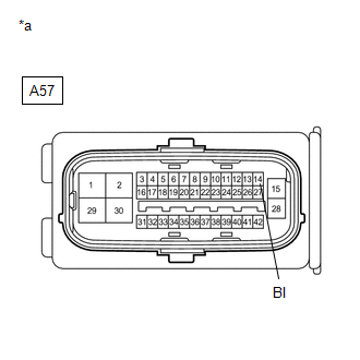
(b) Make sure that there is no looseness at the locking part and the connecting part of the connector.
(c) Disconnect the A57 skid control ECU (brake booster with master cylinder assembly) connector.
(d) Measure the voltage according to the value(s) in the table below.
Standard Voltage:
| Tester Connection | Condition | Specified Condition |
|---|---|---|
| A57-14 (BI) - Body ground | Always | 11 to 14 V |
| NG | | REPAIR OR REPLACE HARNESS OR CONNECTOR (BI CIRCUIT) |
|
| 5. | CHECK HARNESS AND CONNECTOR (BS TERMINAL) |
| (a) Measure the voltage according to the value(s) in the table below. Standard Voltage:
|
|
| OK | | REPLACE BRAKE BOOSTER WITH MASTER CYLINDER ASSEMBLY |
| NG | | REPAIR OR REPLACE HARNESS OR CONNECTOR (BS CIRCUIT) |
READ NEXT:
 Linear Solenoid Valve Offset Learning undone (C1345,C1368)
DESCRIPTION The skid control ECU (brake booster with master cylinder assembly) stores and corrects the individual differences in the brake pedal stroke sensor assembly, actuator solenoids, and stroke
Different Diameter Tire Malfunction (C1348)
DESCRIPTION If the hybrid vehicle control ECU receives a signal from the skid control ECU (brake booster with master cylinder assembly) that the AWD system is malfunctioning, the hybrid vehicle contro
Accumulator Pressure Sensor (C1365)
DESCRIPTION The accumulator pressure sensor is built into the brake actuator (brake booster with master cylinder assembly). The skid control ECU (brake booster with master cylinder assembly) detects t
SEE MORE:
Freeze Frame Data
FREEZE FRAME DATA DESCRIPTION The ECM records vehicle and driving condition information as freeze frame data the moment a DTC is stored. When troubleshooting, freeze frame data can be helpful in determining whether the vehicle was moving or stationary, whether the engine was warmed up or not, wheth
Components
COMPONENTS ILLUSTRATION *1 CENTER EXHAUST PIPE ASSEMBLY *2 EXHAUST PIPE DAMPER *3 FRONT EXHAUST PIPE ASSEMBLY *4 HEATED OXYGEN SENSOR *5 TAIL EXHAUST PIPE ASSEMBLY *6 EXHAUST PIPE SUPPORT *7 COMPRESSION SPRING *8 GASKET N*m (kgf*cm, ft.*lbf): Specified
