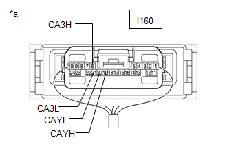
- Resistance between terminals 6 (CA3H) and 21 (CA3L) of the central gateway ECU (network gateway ECU) is 70 Ω or higher.
- Resistance between terminals 19 (CAYH) and 20 (CAYL) of the central gateway ECU (network gateway ECU) is 70 Ω or higher.
Lexus NX: Open in Bus 3 Main Bus Line
Lexus NX Service Manual / Power Source & Network / Networking / Can Communication System / Open in Bus 3 Main Bus Line
DESCRIPTION
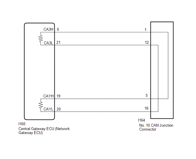
There may be an open circuit in one of the CAN main bus lines when the resistance between terminals 6 (CA3H) and 21 (CA3L) of the central gateway ECU (network gateway ECU) is 70 Ω or higher.
| Symptom | Trouble Area |
|---|---|
| |
|
This malfunction is not related to the lines of a CAN branch or to ECUs or sensors connected to a CAN branch.
WIRING DIAGRAM
CAUTION / NOTICE / HINT
CAUTION:
When performing the confirmation driving pattern, obey all speed limits and traffic laws.
NOTICE:
- Inspect the fuses for circuits related to this system before performing the following procedure.
- Before measuring the resistance of the CAN bus, turn the power switch off and leave the vehicle for 1 minute or more without operating the key or any switches, or opening or closing the doors. After that, disconnect the cable from the negative (-) auxiliary battery terminal and leave the vehicle for 1 minute or more before measuring the resistance.
-
After turning the power switch off, waiting time may be required before disconnecting the cable from the negative (-) auxiliary battery terminal.
Click here
.gif)
-
When disconnecting and reconnecting the auxiliary battery.
Click here
HINT:
When disconnecting and reconnecting the auxiliary battery, there is an automatic learning function that completes learning when the respective system is used.
Click here
-
Some parts must be initialized and set when replacing or removing and installing parts.
Click here
-
Because the order of diagnosis is important to allow correct diagnosis, make sure to begin troubleshooting using How to Proceed with Troubleshooting when CAN communication system related DTCs are output.
Click here
-
After performing repairs, perform the DTC check procedure and confirm that the DTCs are not output again.
DTC check procedure: Turn the power switch on (IG) and wait for 1 minute or more. Then operate the suspected malfunctioning system and drive the vehicle at 60 km/h (37 mph) or more for 5 minutes or more.
-
After the repair, perform the CAN bus check and check that all the ECUs and sensors connected to the CAN communication system are displayed as normal.
Click here
HINT:
- Operating the power switch, any switches or any doors triggers related ECU and sensor communication with the CAN, which causes resistance variation.
- Even after DTCs are cleared, if a DTC is stored again after driving the vehicle for a while, the malfunction may be occurring due to vibration of the vehicle. In such a case, wiggling the ECUs or wire harness while performing the inspection below may help determine the cause of the malfunction.
PROCEDURE
| 1. | CHECK FOR OPEN IN CAN BUS WIRE (NO. 10 CAN JUNCTION CONNECTOR) |
(a) Disconnect the cable from the negative (-) auxiliary battery terminal.
| (b) Disconnect the No. 10 CAN junction connector. |
|
(c) Measure the resistance according to the value(s) in the table below.
Standard Resistance:
| Tester Connection | Condition | Specified Condition | Connected to |
|---|---|---|---|
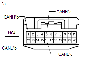
| I164-1 (CANH) - I164-12 (CANL) | Cable disconnected from negative (-) auxiliary battery terminal | 108 to 132 Ω | Central gateway ECU (network gateway ECU) |
| I164-5 (CANH) - I164-16 (CANL) | Cable disconnected from negative (-) auxiliary battery terminal | 108 to 132 Ω | Central gateway ECU (network gateway ECU) |
| OK | .gif) | REPLACE NO. 10 CAN JUNCTION CONNECTOR |
|
.gif)
| 2. | CHECK FOR OPEN IN CAN BUS WIRE (CENTRAL GATEWAY ECU [NETWORK GATEWAY ECU] - NO. 10 CAN JUNCTION CONNECTOR) |
| (a) Measure the resistance according to the value(s) in the table below. Standard Resistance:
|
|
| OK | | REPAIR OR REPLACE CAN MAIN WIRE OR CONNECTOR (CENTRAL GATEWAY ECU [NETWORK GATEWAY ECU] - NO. 10 CAN JUNCTION CONNECTOR) |
| NG | | REPLACE CENTRAL GATEWAY ECU (NETWORK GATEWAY ECU) |
READ NEXT:
 Check Bus 3 Lines for Short Circuit
DESCRIPTION There may be a short circuit between the CAN main bus lines and/or CAN branch lines when the resistance between terminals 6 (CA3H) and 21 (CA3L) of the central gateway ECU (network gateway
Check Bus 3 Line for Short to +B
DESCRIPTION There may be a short circuit between one of the CAN bus lines and +B when there is no resistance between terminal 6 (CA3H) of the central gateway ECU (network gateway ECU) and terminal 16
Open in One Side of Bus 3 Branch Line
DESCRIPTION When the CAN bus main lines are normal (no open, short to ground, short to +B or short between lines) and there is an ECU or sensor on the "Communication Bus Check" screen that is indicate
SEE MORE:
Removal
REMOVAL PROCEDURE 1. REMOVE FRONT SUSPENSION CROSSMEMBER SUB-ASSEMBLY Click here 2. REMOVE FRONT STABILIZER LINK ASSEMBLY LH (a) Remove the nut and front stabilizer link assembly LH. HINT: If the ball joint turns together with the nut, use a 6 mm hexagon wrench to hold the stud bolt.
Components
COMPONENTS ILLUSTRATION *1 OIL FILTER CAP ASSEMBLY *2 O-RING *3 GASKET *4 OIL PAN DRAIN PLUG *5 OIL FILTER ELEMENT *6 OIL FILTER DRAIN PLUG *7 OIL FILLER CAP - - N*m (kgf*cm, ft.*lbf): Specified torque ● Non-reusable part
© 2016-2026 Copyright www.lexunx.com
